RCT2.0 Beta Tester Manual
Beta-tester's Instructions and help for RCT 2.0
(Living document started October 12, 2022, latest significant update Sep 26, 2023/LS)
A proper manual for this version is being worked on as a living document as well.
Introduction
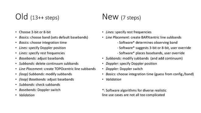
This RCT2.0 was created after a staff presentation in early 2017 where the current (old) way of generating a line resource in the OPT/RCT using the implemented telescope hardware point of view requiring at least 13 steps, depending on how good the initial guess for setting the baseband center was was summarized. This was compared to a desired (new) way with only 7 steps and without any required guess work and accompanying confusions and frustrations. Here the telescope hardware iterative back-and-forth fine-tuning, causing potential undesired shifting of frequency coverage (and missing the targeted line) could be replaced by a science point of view without the observer having to worry about the hardware specific limitations from the start. The final summarizing slide is reproduced below to indicate the targeted changes in RCT2.0 presented here:
First steps on using RCT2.0
The new draft RCT (aka RCT 2.0) has been made available through,
http://webtest.aoc.nrao.edu/rct
Use the same OPT user credentials (also used for the PST at my.nrao.edu), to login.
Once logged in, the initial RCT 2.0 view should mostly resemble the original RCT view with an important difference that may not be immediately obvious. To start testing, [we anticipate this won't be necessary later] please create a new catalog (File → Create New → Catalog) for your new testing resource setup. Then create a new instrument configuration and note that the drop-down menu to create a resource has a single option: create a new instrument configuration instead of the previous 3-bit or 8-bit options (File → Create New → Instrument Configuration).
This pops up a window where one can specify what kind of resource should be created; in reverse order of appearance:
- manual: this resembles the classic way of setting up any resource where the user specifies exactly what they want, step by step. We do not anticipate rigorous testing for this option.
- continuum: this resembles the classic way of setting up a continuum resource with the original resource wizard (assuming this feature was known to you). This would more or less reproduce the NRAO Default resources that then can be edited, e.g., for baseband center frequency. The caveat is that this -- like any of the other options here -- disables the commensal 'realfast' observing obtained with any of the resources in the NRAO Defaults catalog. Doppler corrections are usually not applied; this resource typically uses absolute sky frequencies.
- frequency sweep, line search, or spectral scan: this option is for those that want to observe all or most of a 1GHz or 2GHz baseband in a contiguous chunk of frequency with higher and homogeneous spectral resolution (better than 2 MHz and typically in dual polarization) than the NRAO Default setups or the continuum option above will do. If one or more lines are specified a new algorithm will help, if possible, to suggest the best baseband center to capture the line(s). Typically recirculation is not available for these (128 MHz) wide subbands, although the contiguous subbands can be set to narrower widths likely at the cost of total frequency coverage. Unused basebands can either be interleaved to get a truly homogeneous sensitivity over the entire frequency range (without subband-edge sensitivity-loss effects) or be put on different and perhaps line-free frequency ranges in the band. Doppler corrections for the date of observing and a specific viewing direction are optional and entered after filling and specifying the subbands in the resource.
- spectral line: is the option to make full use of recirculation and stacking of baselineboard pairs to obtain the highest spectral resolution on narrow chunks of frequency centered on specific rest frequencies and which are corrected for Doppler effects on the time and date of the actual observation. Placing the spectral windows between the forbidden regions might be complicated, especially when covering many spectral features, and an attempt is made to solve this for you. As this is not a one hundred percent solvable problem, the user is given some options, including manually editing of the suggested solution; see for example the hints section below. Note that changing the solution may require to start from scratch if manual edits are unsatisfactory. We anticipate that some users will ask the helpdesk for alternatives when they get stuck. Specifying the Doppler direction, and applying Doppler corrections for the date of observing for at least one transition/baseband is required.
From this point it may be helpful to us if you could keep a list/record of actions taken, buttons clicked and baseband/subband adjustments - but also server interruptions - in chronological order. Previous exchanges show that it otherwise is very difficult to remember exactly what was done in case we need to trace back steps to resolve or understand possible problems encountered. However we understand that this may be too much of an effort to ask.
Note that with version 1.32 of the OPT suite, the helpdesk can be reached by simply clicking the "contact support" button available in each resource or through the help drop-down in the menu bar.
Creating a specific spectral line resource
A line setup is created by choosing the "spectral line" option in the Resource Type dialog. Specify the anticipated array configuration to allow the default integration time to be determined later. Giving it a resource descriptive name is also useful, but can be done at any stage following (and the integration time can be changed later as well).
When a line setup is generated, again the view should mostly resemble the view of the classic RCT, but note that the tab order and tab names have been revised and most tabs are not accessible at this point. There are some other minor differences; the resource name and integration time are always visible and editable in the basics table — it is not a tab anymore - and that no a-priori selection of the receiver is requested. The other tabs will become accessible once the information on the previous tab has been completed with the minimum information needed to advance through the tabs to create the resource.
The first tab is the "Doppler Position" tab and is required to allow the proper calculations in the next step/tab. Specifying a valid direction unlocks the "Lines" tab, where the lines may be specified as before (i.e., manually or by uploading a file). Ignore the display at this time because it doesn't know about your lines yet. Here the lines specified with their main Doppler shift (displayed below the rest frequency entered) will determine the receiver band. For the observing-day specific fine-tuning, applying the Doppler tuning is moved further down in the process. For complicated setups or setups with many lines, we strongly suggest to make a line definition file and import that instead of hand editing each line, but we wouldn't mind if you also try hand editing and provide feedback on that as well. Instructions on how to make a line definition (txt) file can be found in the OPT manual.
Note that the line definitions can be selected or de-selected, depending on whether this line should be used in the automated setup. For example, one could define an artificial average line frequency to be used for Doppler setting only, or one would exclude lines that are less important for the science but create difficulties for or undesired behavior of the automated setup, e.g., providing a 3-bit setup as the only possible solution to catch most desired lines whereas an 8-bit setup could be more efficient but only captures the essential lines (plus maybe a few but not all desired lines). Also, sometimes the algorithm will work better if a line is de-selected; the line can be added later using the generate-button in the subbands tab.
The next step is to select the "Basebands" tab and click the "Start Automated Setup" button (*see known issues below). This is the major difference between the current RCT and this new prototype RCT 2.0. It uses an algorithm to replace the guess-work on setting the baseband centers that were the cause of a lot of frustration and unnoticed subband shifts when using the "Generate Lines" tab (see the extensive OPT manual). The algorithm also places the line subbands or spectral windows as specified in the lines tab in the (anticipated) most optimum sections of the baseband or complain when it cannot find a solution without compromising the science (suggesting solutions like removing a line or reducing a velocity coverage). This should make sure that the requested velocity coverage is always captured in the spectral window with the caveat that individual subbands (that are a power of 2 in MHz wider than the requested cover of velocity-frequency width) may not be centered on the line.
The algorithm by default will use the more sensitive 8-bit samplers, unless the lines are spread over more than two chunks of ~1 GHz (the 8-bit baseband width); then the 3-bit samplers (~2 GHz baseband widths) are used. You, as the user can switch between them and also shift the baseband centers by (integer steps of) 128 MHz using the plus/minus buttons without compromising the setup (until a line is not covered by the baseband anymore). Note that the old setup selections are still available under the "Manually Generate Subbands per Line", but we anticipate that these are generally not necessary to be used anymore unless a line was skipped to make the algorithm work and you want to add it back in, or if you want to use a mixed 3-bit/8-bit setup (see below).
The unused basebands (if there are any) at this point probably aren't placed in the most optimal way to capture any continuum (*see known issues below). We are working this out but it should also be possible to manually set their centers at their desired frequencies here and add continuum (128MHz) subbands in the next tab, for example using the "Fill" button method.
The next tab, "Subbands", allows the user to make changes to individual subbands and add more (continuum or line) subbands with the restrictions as before. Adding subbands can be done one-by-one using the "Add" button below the baseband's subbands or by using the "Fill" button at the top (note that there is a "Fill" for all basebands simultaneously as well as a "Fill" for the currently shown baseband). We further trust that the remaining tabs are logical and self-explanatory. Please let us know if you need further help and where we can improve the tool and/or these brief instructions.
Hints to solve issues
- A 3-bit baseband cannot have more than 16 individual subbands, possibly fewer if any of the subbands requires more than four baseline board pairs and definitely fewer if any subband requires more than eight baseline board pairs. Using only fewer than 16 subbands for line work allows to add additional '128 MHz continuum subbands' in that baseband.
- In 8-bit basebands, up to 32 subbands per baseband are allowed. When anticipating more than 16, click on the colored subband ID number to see the number change from any number below 16 to a new number (>=16) and a color change, exposing the so-called "alternate path" or "DP1", for as many subbands as additionally are required (including '128 MHz continuum subbands') before adding these additional subbands to avoid possibly running into the 'column rule' issue.
- When a setup as suggested by the algorithm is not the observer's desired setup, for example when requiring a mixed 3-bit/8-bit mode or when requiring a different distribution of line subbands over the basebands (perhaps to also more evenly spread additional continuum subbands), it may be helpful to use the automated setup with only selecting the lines (in the lines tab) for an anticipated baseband. That is, use the automated setup to find the baseband center for a group of lines, write down the baseband center and repeat the process for the next group of lines; it is okay if the previous baseband setting is lost if the center frequency was captured. When done, switch back on all lines in the lines tab, and move to the basebands tab. Set the individual baseband centers to the values from the previous step and generate the subbands/spectral windows manually, paying attention to the options for which baseband to use for where baseband frequencies overlap. This will provide the optimum baseband centers for the lines that are captured in that baseband, avoiding the 128 MHz boundaries as much as possible.
- If more help is needed, help is available at https://help.nrao.edu
Creating a frequency sweep resource
A frequency sweep setup is created by choosing the "frequency sweep" (or "line search" or "spectral scan") option in the Resource Type dialog. Specify the anticipated array configuration to allow the default integration time to be determined later. Giving it a resource descriptive name is also useful, but can be done at any stage following. Note that here the observing band and samplers need to be selected in advance although all this pre-collected information can be altered at later stages.
Add lines to the lines tab to help guide the setup of the basebands or leave this info blank and move to the "Basebands" tab directly. If lines are specified, the "Start Automated Setup" button will smartly place the basebands as in the line setup (without generating subbands here), otherwise this option is unavailable and the baseband centers would be entered manually in the "Center Frequency" column of the basebands table to define the requested frequency ranges. Be aware that to get homogeneous sensitivity and no 128 MHz separated 'sensitivity drop-out' zones in the frequency coverage (i.e., near the subband edges), the use of overlapping basebands may be necessary, resulting in less total frequency coverage than otherwise is maximally possible.
In the "Subbands" tab use the all-basebands "Fill", select them and use "Bulk Edit" to fine-tune the polarization and number of baseline board pairs (to achieve the homogeneous desired channel separation). Note that the higher frequency bands may already fill the basebands using the maximum of 64 baseline board pairs. It may be necessary to disable (or not by default fill all) subbands and/or basebands to free up baseline board pairs first to be able to obtain higher spectral resolution.
If Doppler corrections are desired, specify the Doppler position and select individual basebands to be corrected in the "Doppler Settings" tab.
Creating a continuum resource
A continuum setup is created by choosing the "continuum" option in the Resource Type dialog. Specify the anticipated array configuration and a resource descriptive name. Note that here the observing band and samplers need to be selected in advance although all this pre-collected information can be altered at later stages.
In the "Basebands" tab, set the desired baseband center frequencies; the subbands should already be filled. When desired, the default continuum parameters of the subbands can be modified in the "Subbands" tab and finally Doppler corrections can be enabled in the "Doppler Settings" tab.
Future expansions
This initial implementation of the RCT does not feature all possible smarts (yet). Future expansions we are actively investigating include, in no particular order (see also below):
- redo the automated setup for a single baseband (reset only one instead of all the basebands, i.e., the entire setup), for example after making a mistake adjusting a single subband or baseband center without loosing the fine-tuning edits made in another baseband
- optional merging of overlapping subbands (although keeping the channel separation unchanged is not always possible due to the reduction of recirculation factor which goes at the cost of stacking more baselineboard pairs in the merging process)
- prioritizing lines covered (in a sequence) other than plain distinguishing essential versus optional (actually, excluded) lines
- for those who end up generating (many, many) subbands manually, it would be useful to have a "generate all" or "generate <baseband>" button
- when individual lines can be grouped with other lines in different overlapping basebands, pre-select which grouping would be preferred or redo the setup with marked lines switching to other basebands than that the algorithm initially had chosen (for example to get a more even distribution of number of lines over the basebands)
- smarter choices on where to center initially unused basebands that can be filled with continuum subbands and a single button to do this filling.
Known Issues
Please be aware of the following:
- Note that the algorithm at this point only uses ~900/1900 MHz of the baseband to avoid placing lines in the baseband sensitivity roll-off regions, so if your lines are spread over e.g. 2000 MHz, two basebands will have subbands instead of a single baseband. We are considering a user override to use the full bandwidth - at your own risk - instead.
- After using the "Start Automated Setup" button, any adjustments made to your setup will disable the ability to change Baseband Options. However, the developer has not had time to include this for all adjustments. We ask that you do not change baseband options after manually adjusting your setup.
- Similarly, once the automated setup is used, the lines in the lines tab are made read-only. If changes to the lines are necessary, e.g., to remove a line from being used in the automated setup, the original suggested setup is not necessarily valid anymore. Unlocking the line editing thus will clear the entire setup (including any manual edits made).
- When rest frequencies are closely separated and velocity coverage is wide, i.e. where individual line subbands overlap, it does not suggest to merge the subbands in a single one centered on the average of the lines. Merging subbands is a scientific choice and at this time best left to the observer, either to be edited afterwards in the subbands tab or by defining an average rest frequency with the appropriate frequency coverage in the lines tab beforehand.
- Whereas the algorithm will accommodate coverage of the requested velocity range around a line, i.e. with some specified width in MHz, the actual subband will be assigned the hardware imposed next factor-of-two MHz width. Due to possible boundary conditions this may result in the subband not to be centered on the line. However, the subband will include the entire requested coverage, albeit thus not symmetrically placed in the subband. This may be unavoidable unless velocity coverage(s) are reduced and/or line(s) are removed from the request (see below).
- The current algorithm to allocate baseline board pairs has a long standing issue: for some complicated setups it will complain to not be able to grant the request and likely refer to the so-called "column rule", whereas the request can be fulfilled manually. We are actively working on this issue and hope to include a fix in the next release. If this issue appears, please contact the user helpdesk at https://help.nrao.edu (and ask for Lorant) for guidance and possible tricks to try to make this work for your specific line setup request.
- It is possible that an observer's request to capture lines with their velocity coverage does not match with the current capabilities of the instrument. The Automated Setup tries to present different options that can be selected with a single mouse click, but it may not come to a final resolution. The solution might be to reduce the velocity coverage for one or more lines or to increase channel separation or perhaps even to de-select some of the optional lines in the lines tab and redo the Automated Setup. As above, it may be helpful to contact the user helpdesk at https://help.nrao.edu (and ask for Lorant) for possible alternatives or tricks for a specific line setup.
At this stage we are mostly interested in the GUI and look-and-feel feedback on this new way of defining the setup, and
we thank you for your time and effort!


Connect with NRAO