Spectral Line Resource Setup for Proposers
Login to RCT-proposing to create a Spectral Line resource.
All completed actions made while working on a resource are automatically saved.
If at anytime RCT-proposing does not load or freezes, try refreshing the webpage and if that does not help, contact the NRAO Science Helpdesk.
Create a Spectral Line Resource
A new resource can only be made in an existing resource catalog. Use File → Create New → Catalog to create one for this project and/or observing semester. After selecting a catalog to store the resource in, File → Create New → Instrument Configuration shows the New Resource Wizard pop-up box with several options to create a new instrument configuration.
To create a spectral line resource select:
- Spectral Line
- Array Configuration: This will set the recommended default correlator integration time, which can be changed later in the tool if desired.
- Name: This should match the name of the resource entered in the proposal submission tool (PST). Note that some characters are not allowed in the RCT and Observation Preparation Tool-suite (OPT) that however may be allowed in the PST; the syntax rules can be found here - please only use RCT allowed characters here and in the PST.
- Finally, select the Generate button.
Basics Table
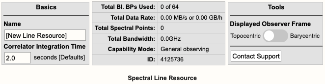
Near the top you will find the Basics info table (Figure 6.1) where you can change the name of the resource and the correlator integration time.
 |
|
Figure 6.1: Spectral line Basics info table. |
Below is a description of the parameters in the Basics table.
| Name |
This should be distinctive from other resources and match the name of the corresponding resource used in the proposal. Do not use special characters and it is probably best to keep the name relatively short. |
| Correlator Integration Time (seconds) |
The correlator integration time would have been set when the resource was initially created by selecting one of the array configurations. This can be modified in the table if you do not wish to use a default setting or if the default is no longer correct once the observing band has been determined. For more details, refer to the Time Resolution and Data Rates section of the Observational Status Summary (OSS). |
| Total Bl.BPs Used |
This indicates the total baseline board pairs (BlBPs) used, which is a measure of the required correlator resources. The starting number will always be zero and will increase as lines and continuum subbands are added and when additional baseline board pairs are stacked on a line. The maximum number of available baseline board pairs is 64. |
| Total Data Rate |
The data rate of the resource will increase with shorter correlator integration times and as lines and continuum subbands are added. Keep in mind the minimum and maximum data rates listed at Time Resolution and Data Rates. |
| Total Spectral Points |
The total number of spectral points will increase as the number of requested BlBPs increases. The number of spectral points in a subband is the product of number of channels, number of polarizations and number of baseline board pairs. The total here is the sum over all subbands. For a more detailed explanation, refer to the Recirculation vs Baseline Board Pairs section of the OPT manual. |
| Total Bandwidth (GHz) |
This will display the sum of all subband bandwidths across all basebands in GHz. This sum has no correction for overlapping subbands but note that overlapping subbands do not physically add to increasing continuum sensitivity. |
| Capability Mode |
This will display the capability mode of a resource, e.g., general, shared risk, or resident shared risk observing. This will depend on the total data rate and certain other settings described in the OSS. |
| ID |
This is the unique resource identification number. |
| Displayed Observer Frame |
The default for frequency calculations and display is Topocentric; the observing frequency for the VLA at a specific time (2000/02/01 at 00:00:00 UT). Frequencies used by VLA Operations Software are stored as topocentric frequencies for the geographic location of the VLA at this specific time. |
| Contact Support |
Selecting this button will allow you to contact the NRAO Science Helpdesk while silently supplying data specific to this resource to the ticket. |
Doppler Position Tab
You may choose to enter the coordinates of a field or group of fields to observe with this resource, or select the option to forgo entering a Doppler position for the proposal stage (though it needs to be defined for the actual observing later). Both options will allow one to continue with the creation of the resource by exposing the proceeding tabs. If you decide to enter a Doppler position at this step, the resource will be viable for import into the RCT-observing UI when the successful proposal is created in the Observation Preparation Tool (OPT) for scheduling block (SB) setup.
Refer to the guidelines for single, multi-source proposals, and complicated resource setups. If you are unsure which path to follow, please contact the NRAO Science Helpdesk.
Lines Tab
In the Lines tab, you may either enter in the line information one-at-a-time by selecting Add Line or import a text file containing a list of lines by selecting:
Import Spectral Lines → Browse (select the txt file containing the lines you want to import/upload) → Upload → Done (if using Firefox)
(If you are using Firefox you will be required to select the Done button after selecting Upload to complete the import. Otherwise, selecting Upload will complete the import.)
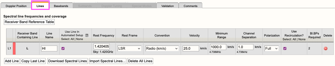
An example of a spectral line added to the Lines tab can be seen in Figure 6.2; for an example text file, see further below.
 |
|
Figure 6.2: Example of a spectral line added to the Lines tab. |
For each line you will need to provide the following information:
| Receiver Band Containing Line |
This will auto-update once the sky frequency is calculated from the other line information entered. |
| Line Name |
This should preferably be the name of the line used in the scientific and/or technical justification. Do not use special characters and keep the name relatively short and descriptive. |
| Use Line in Automated Setup (all/none) |
You may choose which lines are used in the automated setup. This means you can upload a set of lines and only use some of them or use this option as a way to partially automate/manually setup your resource. |
| Rest Frequency |
The rest frequency of the line you wish to observe including the unit (e.g. GHz, MHz, etc). The displayed value below the input field is the calculated observing frequency as determined from the other information in the row. This observing frequency will update with new entries and only differs from the input if the velocity is non-zero and/or if a Doppler position was given earlier. |
| Rest Frame |
The velocity (provided below) is determined using a rest frequency (provided above) and reference frame plus convention. This reference frame is used to calculate the observing frequency. Options are Topocentric, Geocentric, LSR (i.e., Local Standard of Rest, kinematic definition) or Barycentric, where Barycentric is almost identical to Heliocentric. |
| Convention |
The reference frame convention to calculate the sky frequency from the rest frequency uses Optical (km/s), Radio (km/s), Redshift (Z), Relativistic (km/s). The unit displayed indicates which unit is expected for the velocity-value in the next column. |
| Velocity |
The line-of-sight velocity (to be given in the units indicated) at which the line should be observed using the given frame and convention. |
| Minimum Range (km/s) |
Specify the minimum velocity range, a spectral window, that should be covered. Note that a first order bandwidth for this spectral window range will be calculated and displayed below the input field using the line frequency details. The subband bandwidth used to cover this spectral window will be the next wider possible power-of-two value (in MHz). Try to keep the initial bandwidth requirement for the range as narrow as possible for your science to maximize flexibility in placing your anticipated subbands between the 128 MHz boundaries; you can widen them later. In general pre-defining multiple spectral windows of more than 16 MHz (i.e., subbands of 32 MHz and wider) will often give problems in the placing the subbands. |
| Channel Separation (km/s) |
The (maximum) channel separation input field will display the velocity width converted to frequency below the input field, and set the channel separation to the next possible narrower value. |
| Polarization |
Select the observation polarization requirement: Full for polarization measurements, Dual for total intensity (and Stokes V) only, or single polarization: Right or Left circular (or the equivalent X or Y for receivers with linear feeds). The choice of polarization affects the options for channel separation by requiring different levels recirculation and/or number of required BlBPs. |
| Use Recirculation? |
The use of recirculation, where possible, reduces the requirements on total BlBP. The number of BlBPs is limited and thus reducing the demand by enabling recirculation is recommended. |
| Bl.BPs (baseline board pairs) Required |
This will auto-update as the other line information is entered and is dependent on channel separation, polarization and recirculation options. The sum of BlBPs over all lines used (3rd column) cannot exceed 64. |
Below is an example of a line text file for a Spectral Line resource. For more details, refer to the OPT manual. You may also export a set of lines from an existing resource in the proper RCT, i.e., the RCT used in conjunction with the OPT when setting up observations, or from another resource in this special stand-alone RCT-proposing version and upload it here.
#Line name; Rest frequency; Rest frame; Velocity convention; Velocity; Minimum range; Channel separation; Polarization products; Additional specifications
L1; 38.293GHz;    Lsr Kinematic; Radio; -10.5km/s; 31.0km/s; 0.01km/s; DUAL; USE_RECIRCULATION=true
L2; 38452.629MHz; Lsr Kinematic; Radio; -10.5km/s; 31.0km/s; 0.01km/s; DUAL; USE_RECIRCULATION=true
Basebands Tab
Initially, there are two options for generating the spectral lines in their respective basebands, automated and manual.
Automated Setup
This will automatically generate the line coverage in subbands as defined for the lines to be used in the Lines Tab, and properly center the basebands in the receiver band to optimally place the subbands in basebands. Only one receiver band will be activated when your lines are spread over frequencies spanning more than one band. The generated setup is a suggestion and can be modified with the guidance below and/or using the Manual Setup feature.
Note that this algoritm attempts to fulfill the line coverage request in the Lines Tab following recommended practice and keeping in mind technical restrictions. Most setups will benefit from using this algoritm but very specific line coverage requests may be too complicated for this algorithm or even technically impossible. Please contact the NRAO Science Helpdesk if you need help and/or discuss trade-off options.
- If all your lines fall below 4 GHz, i.e., up to the S-band frequency range, one can only use the 8-bit system.
- If all your lines fall within the 4-50 GHz frequency range, the automated setup will select the system which best covers all of the requested lines with their requested velocity coverage. It will default to using the more line-sensitive 8-bit samplers, but in cases where necessary to cover all lines with the desired velocity coverage, it will use the 3-bit system. It will not opt for a mixed 3-bit/8-bit sampler combination, but this can be set manually if desired, e.g., starting from the automatically suggested setup.
- After the automated setup is done, if applicable it may present some options for different baseband settings and/or receiver bands - once manual changes are made please do not select a different option. Further down, it will also show the settings to manually adjust the suggested setup and a table to generate lines manually. You may manually regenerate subbands or make adjustments (i.e., here and in the subbands table) if you do not like what the automated setup has suggested, but be aware that the automatically generated subbands may need to be deleted if you regenerate them manually. This may result in a less favorable coverage; see also Redo Automated Setup. Keep in mind, the mixed-mode 3/8-bit system may be manually selected at this stage and baseband centers can be easily moved without jeopardizing the line setup using the plus and minus buttons.
- Additional continuum subbands always need to be added manually, and is best done after the line subband and baseband configuration has been finalized (either automatically or manually). See below for restrictions in 3-bit and in 8-bit.
- When using the automated setup, be aware of any messages that may appear on the right hand side and bottom of the web interface.
- See below for additional information.
Manual Setup
This is essentially the legacy implementation and will require you to manually select the proper receiver band, the desired sampler system (if applicable), set the baseband centers and generate each line subband one-at-a-time. To see the table of lines and their respective Generate button, scroll down in the Basebands tab.
- The Manual Setup is also used to modify the suggested Automated Setup.
- Shifting the baseband center frequencies can be done in two ways:
- Use the '+' or '-' buttons next to the displayed baseband center frequency. This will keep the optimum subband placing intact by shifting the baseband center frequency by multiples of 128 MHz, thus without changing the relative location of the subbands between the 128 MHz boundaries, or
- Manually enter the desired center frequency, with the caveat of undoing the optimization for placing the subbands away from the 128 MHz boundaries; this may require to delete one or all of the existing subbands and generating new ones using the Generate Table.
- If you shift the baseband center frequency or change the system after using the automated setup, you will need to manually generate a line if it resides in a different baseband.
- Be aware of subbands that "hug" a 128 MHz boundary, which is a common symptom that may indicate an unwanted (and generally unnoticed) subband shift due to changing the baseband center. Unless using the Automated Setup and possibly the +/- buttons, if a subband and 128 MHz boundary "touch" after manually shifting the subband, that subband should be regenerated manually and subsequently may issue new warning messages.
- As always, be aware of any messages that may appear on the bottom of the web interface.
Redo Automated Setup
If you do not like the changes you made after the automated setup, you may select "Redo Automated Setup" and it will remove all manual edits to the resource. Basically, starting over with the automated setup. One reason could be to de-select a less important line from the Lines Tab that causes undesired baseband centers, and another reason could be to capture a specific line subband in another baseband.
Undo Manual Setup
If you wish to (partially) start over with the manual setup, then you will need to manually remove all subbands, or the relevant subbands in specific basebands in the Subbands tab. This can be done in bulk from the Subbands tab.
If subbands overlap or are very close to each other, it may be an option to merge the subbands into one with a new subband center frequency and a wider bandwidth that covers the frequency ranges of the overlapping subbands — note that this typically requires to also change the recirculation factor and/or the number of baseline board pairs to keep the channel separation the same as in the original subbands (which may already need to be deleted before a merged subband can be added to avoid hitting resource restrictions causing problems).
Subbands Tab
In the Subbands tab you now may make any adjustments to the spectral line subbands, i.e., bandwidth (BW), polarization, Bl.BPs (baseline board pair stacking), and Recirculation. From here, excepting the +/- 128MHz buttons, it is best not to touch the baseband center frequency settings anymore. Once the line setup is finalized and resources are available (i.e., check number of subbands in a baseband, total number of BlBPs and the data rate) you may also want to add continuum subbands to the basebands.
The Snap To Grid and Fix To Baseband options are a left-over from the classic way of modifying the setup. The defaults (Snap To Grid and Fix To Baseband checked for continuum subbands, unchecked for line subbands) should be left alone. More information can be found in the description of subbands in the table of the Legacy setup in the OPT manual.
Spectral Line Resolution
The generated line subbands will appear in their respective basebands, typically in the BD samplers before the AC samplers. Note that some line subbands are very narrow and hard to see in the graphics - they will however be listed in the subband details table below the graphics as existing in the setup. Otherwise, when you see a line without a generated subband associated with it, that may simply be a line guide to show you where it may overlap in that baseband. The actual generated line will be in the neighboring baseband with a similar frequency range. The user may make adjustments to the bandwidth (BW), polarization, and the channel separation covering a line by adjusting the number of BlBPs and recirculation. For more details on stacking BlBPs and increasing recirculation, please refer to the Recirculation vs Baselineboard Pairs section of the OPT manual.
- If subbands overlap or are very close to each other, it may be an option to merge the subbands into one with a new subband center frequency and a wider bandwidth that covers the frequency ranges of the overlapping subbands — note that this typically requires to also change the recirculation factor and/or the number of baseline board pairs to keep the channel separation the same as in the original subbands (which may already need to be deleted before a merged subband can be added to avoid hitting resource restrictions causing problems). When merging subbands one can (re-)use the algorithm to place the subbands, provided that there is a new line defined (with an average rest frequency and merged velocity coverage) and the founding line definitions in the Lines Tab are de-selected for inclusion in the algorithm.
- You may also shift the baseband center frequency by +/- 128MHz from within the Subbands tab. (Again, you may need to manually generate a line if it resides in a new baseband.)
Add Continuum Subbands
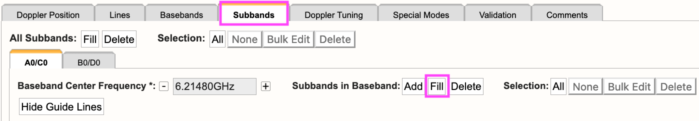
For each baseband, within the restrictions outlined below, continuum subbands can be added one-at-a-time or by using the recommended Fill button at the "Subbands in Basebands" level (see Figure 6.3). Note, the bulk edit mode of the Fill option will not alter the generated spectral lines.
Manually adding subbands one-at-a-time will require the user to select the Add button, then select the central frequency range of each continuum subband by choosing the desired range in the drop-down menu located in the subbands table.
 |
|
Figure 6.3: Adding continuum subbands in the Subbands tab using Fill. |
After selecting Fill, the user will be presented with a pop-up box containing the following parameters:
| Bandwidth |
This defines the bandwidth of each continuum subband, typically left to 128 MHz except for the lowest frequency bands (where the receiver bandwidth is limited). |
| Number of Subbands |
The maximum number of subbands per baseband will vary depending on the sampler mode (3-bit or 8-bit) and how many baseline board pairs have been used so far by the generated spectral lines. |
| BlBPs |
Number of Baseline Board Pairs (BlBPs) to stack per subband, typically one (see description in Lines tab above). More baseline boards will reduce the channel separation in a subband. Check that there are enough available to fill the number of subbands as each of the subbands is filled with the same number of BlBPs. |
| Polarization |
Full (RR, LL, RL, and LR), Dual (RR and LL), or single (RR or LL), typically left to Full (see description in Lines tab above). |
| Array Summing |
This is for special observing modes; typically leave as is. |
| Recirculation |
Typically left to one as 128 MHz subbands are used (where recirculation is not possible). For narrower subbands recirculation can be used to decrease the channel separation without increasing the number of BlBPs (see description in Lines tab above). |
| Place first subband in Grid |
As the edges of the basebands are less sensitive, the default is to start at the second interval/boundary of 128 MHz from the start of the baseband frequency coverage (i.e., avoid the first 128 MHz), assuming the baseband cannot be covered completely with continuum subbands (due to hardware limitations). You may change this to start at a different boundary, e.g., #1 if the entire baseband still can be covered with continuum subbands. |
Doppler Tuning Tab
Doppler Position Off
If you chose not to enter a Doppler position on the first tab, then you will not be asked to enable the Doppler tuning. The contents of this tab will not be visible. Note that for actual observing, as opposed to just proposing for observations, a Doppler position has to be defined (i.e., at a later stage).
Doppler Position On
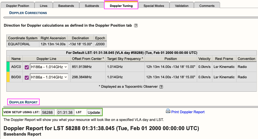
If you chose to enter a Doppler position on the first tab, then you will be required to enable the Doppler tuning for at least one baseband. This will also enable a Doppler Report located below the Doppler tuning settings (see Figure 6.4).
 |
|
Figure 6.4: Doppler Tuning tab showing an example of a Doppler Report. |
You may update the report to view the setup for a given VLA LST day and time. This will recalculate the values in the baseband tables below and will allow you to see what the on-the-sky values ("Script Computed Center Frequency" column) will be on the set day and time. The default values are 58288 01:31:38 LST which translates to 2000Feb01 00:00:00 UT.
Special Modes Tab
RFI blanking can be enabled for the entire resource. For more details, refer to the OPT manual. Note, this is not a required step for the proposal process and can be turned on/off during observation preparation in the RCT prior to observing.
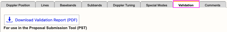
Validation Tab
When you are satisfied with the resource setup and it validates (check the messages in the bottom frame of the page), select the Download Validation Report (PDF) button (see Figure 6.5). Attach this PDF to the proposal in the PST.
 |
|
Figure 6.5: Download the valid resource to a PDF. |
If the resource does not validate and it's not clear why, contact the NRAO Science Helpdesk via the RCT (preferably using the Contact Support button in the Tools table at the top right of the page, directly below the graphics). Contacting us this way will append a resource identification and a log file to the ticket so we can take a deeper dive into the errors specific to this resource.
Comments Tab
You may provide comments as notes to yourself for future reference. This will only be seen by you and will not be printed to the PDF on the Validation tab.
Hints to solve issues
- Only 64 BlBps are available; make sure not to require more than that number, also when adding continuum subbands.
- A 3-bit baseband cannot have more than 16 individual subbands, possibly fewer if any of the subbands requires more than four baseline board pairs and definitely fewer if any subband requires more than eight baseline board pairs. Using only fewer than 16 subbands for line work allows to add additional '128 MHz continuum subbands' in that baseband.
- In 8-bit basebands, up to 32 subbands per baseband are allowed. When anticipating more than 16, click on the colored subband ID number to see the number change from any number below 16 to a new number (>=16) and a color change, exposing the so-called "alternate path" or "DP1", for as many subbands as additionally are required (including '128 MHz continuum subbands') before adding these additional subbands to avoid possibly running into the 'column rule' issue.
- When a setup as suggested by the algorithm is not the observer's desired setup, for example when requiring a mixed 3-bit/8-bit mode or when requiring a different distribution of line subbands over the basebands (perhaps to also more evenly spread additional continuum subbands), it may be helpful to use the automated setup with only selecting the lines (in the lines tab) for an anticipated baseband. That is, use the automated setup to find the baseband center for a group of lines (keeping in mind the number of subband restrictions for 3-bit and 8-bit listed above), write down the baseband center and repeat the process for the next group of lines; it is okay if the previous baseband setting is lost if the center frequency was captured. When done, switch back on all lines in the lines tab, and move to the basebands tab. Set the individual baseband centers to the values from the previous step and generate the subbands/spectral windows manually, paying attention to the options for which baseband to use for where baseband frequencies overlap. This will provide the optimum baseband centers for the lines that are captured in that baseband, avoiding the 128 MHz boundaries as much as possible.
- More help is available at the NRAO Science Helpdesk.
Notes and Known Issues
This initial implementation of the RCT does not feature all possible smarts (yet). We do have a list of future expansions and improvements that is too large to list here. Please be patient in asking for new features - it is likely we have them on our list already and are working on implementing them in the foreseeable future.
Also, please be aware of the following:
- Note that the algorithm for the Automated Setup at this point only uses ~900/1900 MHz of the baseband to avoid placing spectral windows in the baseband sensitivity roll-off regions, so if your line coverage is spread over e.g. 2000 MHz, two basebands will have subbands instead of a single baseband. The Manual Setup procedure can make use the full bandwidth to place your subbands in a wider range - at your own risk.
- The Automated Setup will place as many line subbands in a baseband as possible before adding subbands to another baseband; this may create heavily uneven number of subbands between the basebands. To improve this, use the hint/trick described above where a baseband center is determined for each group of line subbands which then are manually generated.
- After using the "Start Automated Setup" button, any adjustments made to your setup will disable the ability to change Baseband Options.
- Similarly, once the Automated Setup is used, the lines in the lines tab are made read-only. If changes to the lines are necessary, e.g., to remove a line from being used in the Automated Setup, the original suggested setup is not necessarily valid anymore. Unlocking the line editing thus will clear the entire setup (including any manual edits made).
- When rest frequencies are closely separated and velocity coverage is wide, i.e. where individual line subbands overlap, the Automated Setup does not suggest to merge the subbands in a single one centered on the average of the lines. Merging subbands is a scientific choice and at this time best left to the observer, either to be edited afterwards in the Subbands Tab or by defining an average rest frequency with the appropriate frequency coverage in the lines tab beforehand. Note that merging subbands and keeping the same channel separation will have an impact on the required number of BlBPs and thus may not be a valid option.
- Whereas the Automated Setup algorithm will accommodate coverage of the spectral window, the requested velocity range around a line, i.e. with some specified width in MHz, the actual subband will be assigned the hardware imposed next factor-of-two MHz width. Due to possible boundary conditions this may result in the subband not to be centered on the line. However, the subband will include the entire requested coverage, the spectral window, albeit thus not symmetrically placed in the subband. This may be unavoidable unless velocity coverage(s) are reduced and/or line(s) are removed from the request (see below).
- The current algorithm to allocate baseline board pairs has a long standing issue: for some complicated setups it will complain to not be able to grant the request and likely refer to the so-called "column rule", whereas the request can be fulfilled independently outside this web-based tool. We are actively working on this issue. If this issue appears, please contact the NRAO Science Helpdesk for guidance and possible tricks to try to make this work for your specific line setup request.
- It is possible that an observer's request to capture lines with their velocity coverage does not match with the current capabilities of the instrument. The Automated Setup tries to present different options that can be selected with a single mouse click, but it may not come to a final resolution. The solution might be to reduce the velocity coverage for one or more lines or to increase channel separation or perhaps even to de-select some of the optional lines in the lines tab and redo the Automated Setup. As above, it may be helpful to contact the NRAO Science Helpdesk for possible alternatives or tricks for a specific line setup.


Connect with NRAO