Planning for Good Polarization Calibration
Introduction
When observing in any of the continuum modes the cross hand products (RL and LR) are produced automatically by the correlator for each IF. Typical "impurities" of the feeds are about 5% for the center of most VLA bands and degrade toward the band edges and away from the pointing center in the image plane. Without any polarization calibration an unpolarized source will appear to be polarized at the ~1% level. Furthermore, without calibration of the R-L phase difference, the polarization angle is undetermined. Fortunately it is not difficult to obtain a reasonably good polarization calibration under most circumstances. With a modest investment of time spent on calibrators and a little effort the instrumental polarization can be reduced to less than 0.1%.
Determining the Leakage Terms (aka D-terms)
The best way to determine the leakage terms (which produce the instrumental polarization), is to observe an unresolved source over a wide range in parallactic angle. The polarization of the calibrator will appear to rotate in the sky with parallactic angle while the instrumental contribution stays constant. The AIPS task PCAL uses this behavior to simultaneously solve for the source polarization properties and the leakage terms. The usual recommendation is for 5 or more observations covering 100 degrees or more of parallactic angle in roughly uniform steps. Strong and compact calibrators (code "P") sources are preferred, although often a reasonably good solution can be obtained from a weaker calibrator observed many times throughout a run for gain and phase calibration. More than one source can be used in the solution provided all sources are unresolved. Algorithms have also been developed in AIPS recently (for VLBI polarization calibration) that allow the use of a single resolved calibrator. In planning an observing run it may be useful to consult the parallactic angle diagram below:
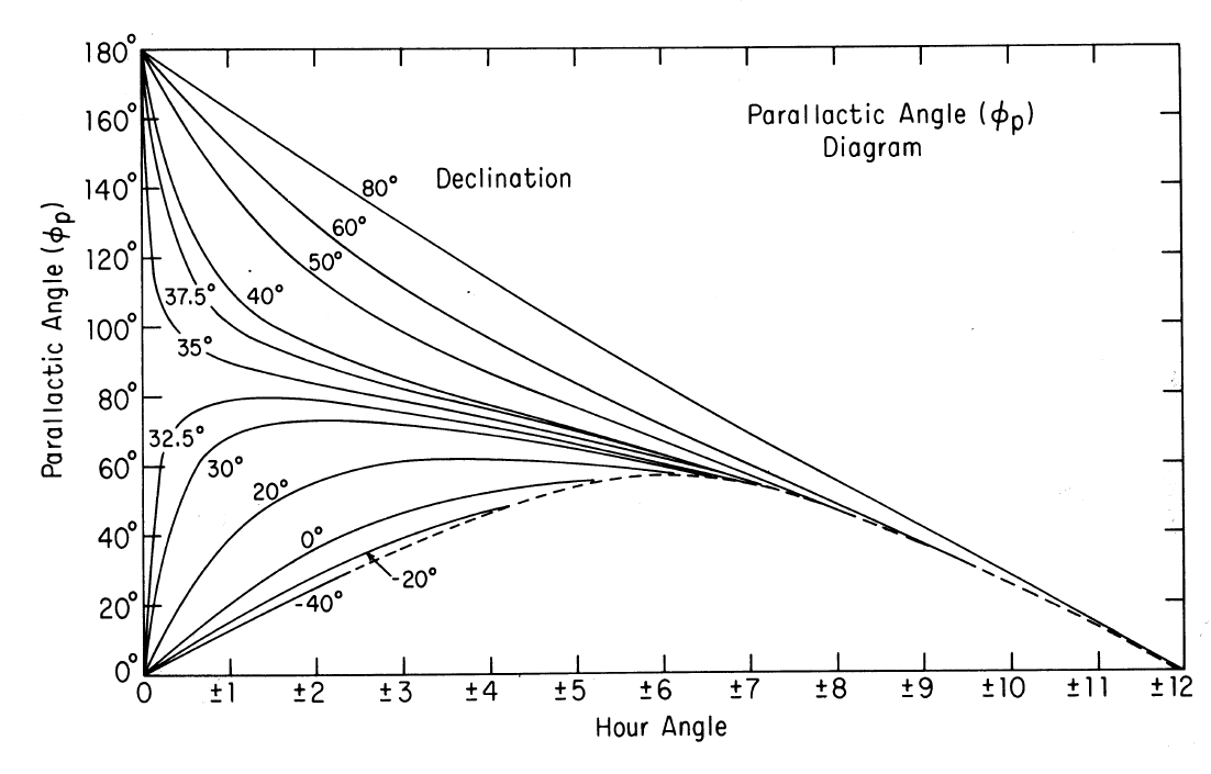
Figure - Parallactic Angle vs. hour angle for various declinations
The leakage terms are also known to be time-variable (Holdaway, Carilli & Owen 1992, VLA test memo #163) and software has been developed in AIPS++ to contend with this variability.
A single observation of a strong unpolarized source (or a source with well known polarization properties) can be used to determine the leakage terms. As an example, 3C84 is strong, unpolarized and unresolved for most VLA frequencies and configurations, so that a single scan on 3C84 may be sufficient. The leakage terms are also fairly constant over weeks to months, so that measurements from one observing run can be passed to another made using the same frequencies and bandwidths and observed in the same configuration. The leakage terms are carried entirely in the antenna table, so to transfer them one merely copies the antenna table.
Calibrating the absolute polarization angles
Calibration of the absolute polarization angle (or R-L phase difference) can be accomplished with a single observation of a polarized source having a known polarization angle (the true R-L phase difference will be twice the source polarization angle). The best source for these purposes is 3C286, which is also a primary flux density calibrator. If 3C286 can't be reached then 3C138 will work in most circumstances. Some information is known about 3C48 and 3C147 as well. All observations of polarization angles summarized below are tied to 3C286 which is assumed to have a Faraday Rotation Measure of 0 rad m$^{-2}$.
| 1995.2 Polarization Measurements | ||||||||||||
| Showing R-L Phase Difference (degrees) and Fractional Polarization (%) | ||||||||||||
| Source | 20cm | 6cm | 3.7cm | 2cm | 1.3cm | 0.7cm | ||||||
| 3C48 | N/A | 0.5 | -148 | 4.1 | -132 | 5.3 | -135 | 7.0 | -145 | 7.6 | -166 | 9.2 |
| 3C138 | -18 | 7.9 | -22 | 11.1 | -22 | 11.9 | -24 | 10.8 | -30 | 10.6 | -23 | 11.6 |
| 3C147 | N/A | <0.1 | N/A | <0.1 | -57 | 0.8 | 110 | 3.1 | 145 | 4.2 | 180 | 5.2 |
| 3C286 | 66 | 9.4 | 66 | 11.0 | 66 | 11.7 | 66 | 12.0 | 66 | 12.0 | 66 | 12.5 |
| 1999.2 Polarization Measurements | ||||||||||||
| Showing R-L Phase Difference (degrees) and Fractional Polarization (%) | ||||||||||||
| Source | 20cm | 6cm | 3.7cm | 2cm | 1.3cm | 0.7cm | ||||||
| 3C48 | -60 | 0.4 | -148 | 4.1 | -138 | 5.6 | -134 | 7.0 | -146 | 8.2 | -172 | 8.8 |
| 3C138 | -15 | 8.0 | -20 | 11.4 | -22 | 11.7 | -24 | 11.7 | -30 | 11.6 | -28 | 12.2 |
| 3C147 | N/A | <0.1 | 16 | 0.4 | -54 | 0.7 | 109 | 2.9 | 147 | 4.5 | 170 | 6.5 |
| 3C286 | 66 | 9.4 | 66 | 11.2 | 66 | 11.6 | 66 | 12.1 | 66 | 12.4 | 66 | 13.3 |
No ionospheric correction has been made to these data, and fluctuations in the ionospheric Faraday rotation, especially approaching the solar maximum in 1999, could cause an error in the above determinations by 10 degrees or more at 20cm. As 3C48 is only weakly polarized at 20cm, it should not be used at this frequency. If it must be used (e.g. no suitable calibrator was observed) then the polarization angle given at epoch 1999.2 can be used. 3C48 may also be undesirable at 22 and 43 GHz where it is weak and variable. At 90cm all the above sources are unpolarized. Some pulsars, however, are strongly polarized and we are investigating using these along with good ionospheric models and data to obtain polarization calibration at 90cm. Contact Rick Perley (rperley@nrao.edu) for further information.


Connect with NRAO