Additional Resource Features and Restrictions
Although the VLA data transmission and correlation is very flexible, there are some restrictions. An overall restriction is that there are only a total of 64 baseline board pairs available. The transmission restrictions, most notable in the higher frequency bands (K, Ka, and Q) are noted further below. The correlator restrictions and a possible remedy are described here first.
32 Subbands per 8-bit Baseband - Data Path One
The nominal data path through the correlator is configured to yield up to 16 subbands per sampling baseband; this nominal data path is internally referred to as “DP0”. There are four 3-bit sampler basebands (in pairs of two spanning up to 5 GHz, a 3-bit transmission restriction) and two 8-bit sampler basebands. For plain continuum, these basebands will be (typically) assigned 16 or 8 “continuum subbands” of 128 MHz to cover the entire baseband frequency range (except for observations below 2 GHz). If one defines subbands for spectral line work, either by using the automated setup or setting them up manually, the distribution of the line subbands will determine the allowed number of subbands available for continuum in each baseband. We recommend defining the line subbands before defining the continuum subbands if line observations are the goal.
Continuum or frequency-sweep observations in 3-bit or 8-bit will generally not have any issues with the number of basebands in DP0 although other restrictions like the maximum number of baseline board pairs and maximum data rate still apply.
Spectral Line Work in 3-bit
A baseband with N assigned line subbands will have room for (16-N) continuum subbands. That is, in 3-bit setups the maximum number of subbands per baseband is always 16 and the stream will always use the nominal data path (i.e., DP0); unused subbands in a (or an unused) baseband cannot be reassigned to function as extra subbands in other basebands. The “Fill option” in the subbands tab in the RCT should only define up to (16-N) 128 MHz subbands (using a baseline board pair each) as determined for each of the four basebands, keeping in mind the total maximum of 64 baseline board pairs for the entire (line+continuum) setup. If the distribution of the continuum subbands over the basebands is not as desired, and all 16 subbands in a baseband have been assigned, it may be possible to move particular line subbands from one baseband to another and moving the continuum subbands in the opposite direction.
Spectral Line Work in 8-bit
Identical to the 3-bit case, the nominal data path, DP0, allows for 16 subbands in an 8-bit sampled baseband, whether used for line or continuum. As the full baseband frequency coverage can be met with eight subbands already, there will be no restrictions for up to eight line subbands defined per baseband and the Fill option in the RCT will insert additional subbands in each of the two 8-bit basebands as listed below. Note that there are different ways to invoke the Fill option with details on possible corrective actions below.
When more than eight subbands in a baseband are defined for spectral line work and it is not possible or desired to distribute the line subbands over both basebands to end up with eight or fewer line subbands in each of the basebands, adding the full baseband frequency coverage with eight continuum subbands to yield more than 16 subbands in an 8-bit baseband is possible but a little more tricky. The addition of subbands over the nominal 16 subbands in a baseband is possible because there are only two, not four, basebands in use and the extra hardware to double the number of subbands for 3-bit observing are not utilized. The 16 subbands allocated to each of the two unused basebands otherwise used in a 3-bit setup can now be reassigned to each of the 8-bit basebands using an alternative data path, internally referred to as “DP1” (data path one). Note that 3-bit cannot use this DP1 as the hardware necessary is already being used. Triggering the additional hardware reassignment to the 8-bit setup then allows for up to 32 subbands per baseband, i.e., leaving up to (32-8=) 24 subbands per baseband that can be configured for line observations while retaining the full 8-bit continuum frequency coverage. Of course, more than 24 subbands can be configured for line observations by sacrificing some of the intended continuum subbands in that baseband.
Adding subbands using the “Fill option” in the RCT and warnings about “DP1”
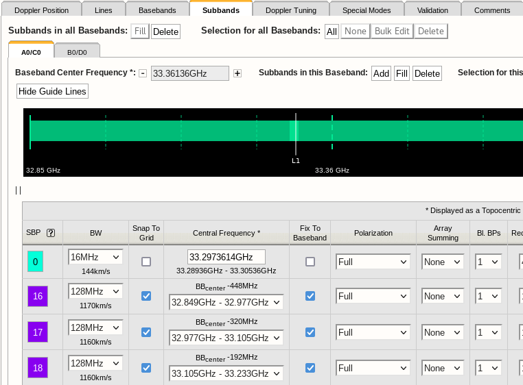
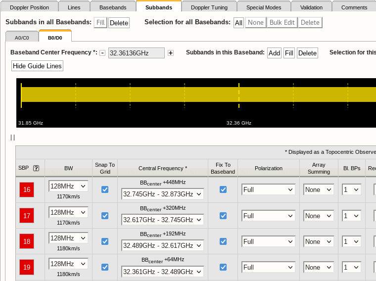
As mentioned before, it is highly advisable to specify the line setup before adding continuum subbands. It is also important to know that “DP0” should always be invoked for every baseband; a baseband configured to only invoke subbands in “DP1” will not yield data and actually stop observing. Therefore the following precautions should be taken when using the Fill option after finalizing the line portion of a resource - this assumes to be in the Subbands tab of the resource with the Figures 3.6.1 and 3.6.2 below for reference:
- Selecting the “Fill” next to “Subbands in all Basebands” on the left above the individual baseband tabs
- By selecting the Fill option for all basebands simultaneously, a total of (8-N) 128 MHz full polarization subbands will be added to each of the two basebands (N can be different for each baseband) to yield a total of eight (line+continuum) subbands. To obtain the maximum continuum coverage, an additional N continuum subbands should be added manually for each baseband (using the buttons at the top or bottom of the table) - check both baseband tabs. Note that the continuum subbands in the basebands, the subband pair identifier (SBP) at the left hand side of the table (e.g., Fig 3.6.1) will have a different color than the color of the baseband in the top graphic and start with number 16 indicating that these subbands are using DP1.
- In the case that there are no subband pair identifiers (SBP) with numbers below 16 (or in the color of the subband in the graphic at the top, e.g., Fig 3.6.2), for example by having no line subbands placed in the baseband by the automated setup or by having deleted all line subbands using DP0, click the colored square of one of the subbands to change its color to the default (as in the top graphic, e.g., Fig. 3.22a) and the number to zero (i.e., below 16) to invoke DP0. There is no need to do this for all possible subbands; once is enough.
- Selecting the “Fill” next to “Subbands in this Baseband” on the right of the baseband frequency in the individual baseband tabs
- By selecting the Fill option for each specific baseband, up to 32-N subbands can be added with more specific parameters (bandwidth, polarization, etc). If no line subbands are defined in the baseband, it will fill using DP0 until 16 are used up, then it will assign subbands to DP1. Otherwise, with predefined line subbands, the first 16 additional subbands will use DP1, the remainder will be configured using DP0. Either way, it is likely that there will be a subband defined using DP0 (unless they are deleted manually) and it should only be checked for having at least one subband in DP0 - a SBP number below 16 and in the color of the baseband in the graphic on top - per baseband.
- Selecting "Add Subband To Baseband" at the bottom of the table of subbands in an individual baseband tab
- Not using “Fill” but manually adding a subband to a baseband at a time will start using DP0 until 16 subbands are defined and continue to use DP1 for additionally added subbands. Again, make sure to check that at least one subband is using DP0.
 |
|---|
|
Figure 3.6.1: Correct use of data path 0 and 1 in a single baseband. Note, the change in color indicates which subband uses the additional hardware (in 8-bit). |
|
|
|
Figure 3.6.2: Incorrect use of data path 1 in a single baseband. At least one SBP should be toggled to enable data path 0 (in 8-bit). |
Ka-band Transmission Restrictions
There is an issue with specifying the frequency of IF pair AC at Ka-band. That is, tuning any part of the AC IF pair band below 32.24 GHz will not result in valid data, regardless whether this is A0/C0 or any of A1/C1 or A2/C2. Only the BD IF pair can be tuned to frequencies below 32.24 GHz; use the BD IF pair instead of AC IF pair when you only need one IF pair for your resource with a frequency tuning below 32.24 GHz. If the RCT validation detects that any part of the bandwidth of IF pair AC is tuned below this 32.24 GHz it will try to swap the AC IF pair with the BD IF pair. If this is not possible, it will issue an error (in red font) in the interface feedback strip if this frequency is specified as a fixed sky frequency. It will issue a warning (blue font) for rest frequencies, as the particular tuning depends on the details of observing date, telescope pointing direction and source velocity definitions. Note that a rest frequency above 32.24 GHz may shift to below 32.24 GHz once it is assigned to a scan in the OPT. This should give you an error in the OPT; you should be aware of this possibility and pay attention to this. However, it is better to assign IF pair BD to the resource if you anticipate this might happen, if you still have this freedom in your resource of course.
When observing very close to 32 GHz with both IF pairs, some combinations where frequency coverage of AC and BD are overlapping are not possible. Consult the NRAO Science Helpdesk for options, preferably before submitting the proposal.
The very wide bandwidth of the Ka-band receiver, from 26.5 to 40 GHz, would suggest that IF pair separations of up to ~13 GHz are possible. Restrictions in the signal path, however, limit this separation to 10 GHz (or any part of the basebands to within 12 GHz). The RCT validation will issue an error if the separation between IF pair centers of AC and BD is more than 10.5 GHz in sky frequency (with IF pair AC tuned to have the higher frequency centers). A separation of more than 10.5 GHz in rest frequency will result in a warning as, e.g., highly red-shifted lines may end up with less separation when the actual sky frequencies are calculated.
K and Q-band Transmission Restrictions
If you choose the RF signals in the different IF paths to be separated by a large amount, it is possible that the RCT will only let you create a resource where the baseband frequency center(s) in IF pair AC is higher than the baseband frequency center(s) in IF pair BD, similar to the Ka-band restriction above.


Connect with NRAO