Introduction, Nomenclature, and Defaults
To access the Resource Catalog Tool (RCT), either login to the OPT Suite via the OPT (https://obs.vla.nrao.edu/opt) and select Instrument Configurations in the navigation strip, or you may use the following URL: https://obs.vla.nrao.edu/rct. Note, to exit the tool properly, use the Exit link in the upper right corner or log out with FILE → EXIT; do not close the browser window/tab until you are properly logged out of the tool.
On the left-hand column of the RCT, you will see an icon menu at the top, NRAO default catalogs along with an empty Personal Catalog you may populate, and possibly other catalog(s) (Figure 3.1.1). Note that an empty resource catalog for each of your successful proposals may be created. You may use this catalog to create personal resource setups or copy/paste NRAO default resources for easy access when creating SBs.
If you have any questions, you may either submit your questions through the NRAO Science Helpdesk or request help directly from the RCT by selecting HELP → CONTACT SUPPORT.
 |
|---|
| Figure 3.1.1: Left-hand column of RCT. |
Nomenclature
As per the SCT, for orientation and to get a feel for the tool(s), it is instructive to walk through the NRAO Defaults catalog. After this orientation it should be almost intuitive to create your own personal resource catalog(s) which you will use in your project's SB scans or help to understand how to use one of the standard wide band resources provided in the NRAO Defaults catalog.
Important Note: Data from the WIDAR correlator is different from the old VLA correlator: the data is always delivered in spectral line or pseudo-continuum mode, similar to Very Long Baseline Interferometry (VLBI). When referring to continuum below, it is meant to refer to data taken for wide band observation purposes: the data itself is divided in frequency channels, but the scientific interest is in the data averaged over all channels and not in individual channels with line emission (or absorption). The latter is referred to as spectral line data. This is the difference in obtaining a two-dimensional image of the sky versus a three-dimensional image cube, where the data retains that different frequencies show different (two-dimensional) sky images.
The best continuum sensitivity is obtained using the maximum available bandwidth in the most sensitive part of the observing band, and thereby avoiding Radio Frequency Interference (RFI) as much as possible. The resource which gives the best performance in each observing band is defined in the NRAO Defaults catalog. To describe the setups, is it useful to understand how the basic generalized path of the radio frequency (RF) signals collected by the receivers in the antenna are delivered through the intermediate frequency (IF) electronics to the WIDAR correlator and where the correlated data ends up in a data set.
Baseband Pairs
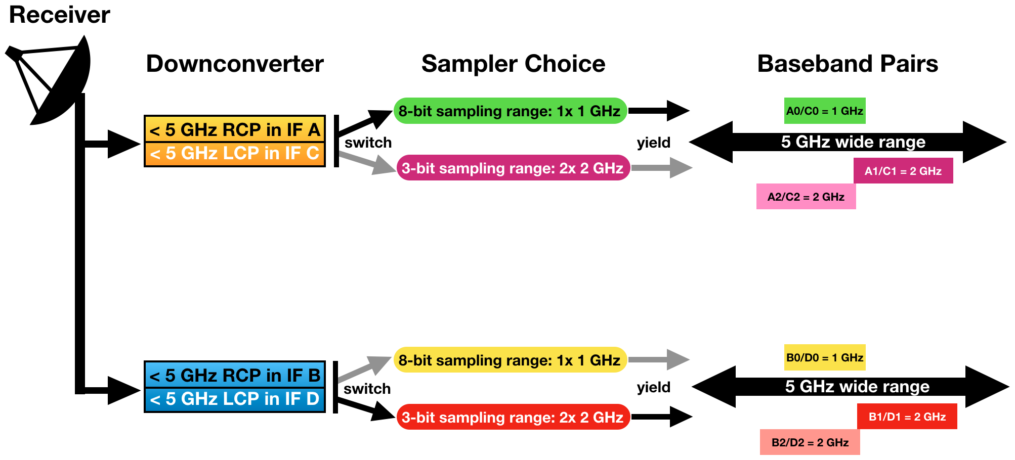
The receiver in the antenna passes (up to) 5 GHz down-converted frequency of the RF receiver bandwidth to four signal paths (Figure 3.1.2); two right circular polarization signals (RCP), labeled IF A and IF B, and two left circular polarization signals (LCP), labeled IF C and IF D. IF A and IF C (i.e., one RCP and one LCP) signals are tuned to the same RF frequency and thus may produce a Stokes I signal from the source. IF B and IF D are also tuned to the same frequency, which typically is not the same tuning as for IF A and IF C. These IF signals are then sampled independently using 8-bit samplers or 3-bit samplers. The VLA Samplers section of the OSS should aid in which sampler to use for your observations. The 8-bit samplers each yield a one 1 GHz wide frequency range containing a corresponding 1 GHz down-converted RF range. The 3-bit samplers each yield two 2 GHz wide frequency ranges containing two corresponding 2 GHz down-converted RF ranges. Per IF path (AC or BD) the two 2 GHz ranges from the 3-bit samplers must be within a total range of 5 GHz and are typically placed to yield a continuous 4 GHz RF bandwidth per IF path, or an 8 GHz RF bandwidth total.
The individual sampled frequency ranges are referred to as basebands, in particular baseband pairs when a combination of simultaneously tuned RCP and LCP signals is involved. The 8-bit samplers yield 1 GHz baseband pairs which are labeled A0/C0 or B0/D0, depending on the original IF path. The 3-bit samplers produce 2 GHz baseband pairs labeled A1/C1 and A2/C2 as sampled from IF path AC, or B1/D1 and B1/D1 if the signals are sampled from IF path BD. These baseband pairs are then transported over optical fiber from the antennas to the correlator.
Part of setting up the resource is to specify which samplers are used and to specify the baseband pair center sky frequencies.
 |
|---|
| Figure 3.1.2: Schematic of nomenclature and the involvement of the 8-bit and/or 3-bit samplers. |
Subband Pairs
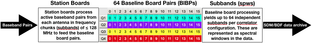
When the basebands from each antenna reach the correlator room, they are fed in 128 MHz bandwidth intervals into station boards. This regular pattern of 128 MHz creates a fundamental interval boundary which cannot be observed, nor included in processing of nearby frequencies. Apart from the baseband edges, there are 7 of such un-observable frequency boundaries per 1 GHz (1024 MHz) baseband when using the 8-bit sampler, and 15 per 3-bit sampler baseband (i.e., per 2 GHz, per 2048 MHz). Note that since this is an odd number, the chosen baseband center sky frequency can never be observed: do not place the baseband center at the frequency of your spectral line. From each 128 MHz chunk, the station boards determine which part (central frequency and frequency width) is forwarded to the correlator for processing. That is, per polarization for each 128 MHz bandwidth, it is determined whether the signal should be forwarded to the correlator, and whether each 128 MHz bandwidth should be divided in powers of 2 and tuned to another center frequency within the 128 MHz range: provided that the frequency interval does not cross the boundary when forwarded to the correlator.
The filtered and tuned frequency ranges delivered by the station boards are referred to as subbands, in particular subband pairs for simultaneously tuned RCP and LCP signals. The individual subbands are at most 128 MHz wide, and independently tunable in frequency if reduced in width by powers of two without crossing the 128 MHz boundaries. Per resource, up to 64 subband pairs can be defined.
Part of setting up the resource is to specify the frequency tuning and frequency width of the subbands that are to be used.
Baseline Board Pairs (BlBPs)
The resulting subband pairs per antenna and IF path are presented to one of the four correlator quadrants for processing by pieces of hardware known as baseline boards, or baseline board pairs (BlBPs) when the subband contains both RCP and LCP signals. Figure 3.1.3 (below) is a simple visualization of the correlator components. Up to 64 BlBPs process the baseband pair streams from the antennas as formatted by the station boards in four quadrants (Q1-Q4) with 16 BlBPs per correlator quadrant. A single BlBP can only receive data from a single subband for processing. Per BlBP 256 correlation products can be computed, where the number of products is the number of polarization products (1, 2, or 4) times the number of spectral frequency points (256, 128, or 64). Within the limits of the number of baseline boards in a correlator quadrant, more than one baseline board can be assigned to process a single subband pair (thus up to 16) at the cost of processing other subband pairs.
A resource defines the output of the station boards (after defining the baseband pairs at the antennas) and the assignment of the available BlBPs for processing to yield up to 64 independently configurable subbands with spectra. These subbands will end up as a simultaneously observed subset of spectral windows (spws) in the visibility data. At most, one subband (of 128 MHz or less bandwidth) can be processed per BlBP, but more than one BlBP can be used to process the same subband (called baseline board stacking), yielding a larger number of channels to obtain an increased spectral resolution over the bandwidth of that subband (in the case without recirculation). In other words, baseline board stacking utilized by assigning more than one baseline board to a single subband. Without recirculation, the combination of subband width, number of polarization products and number of baseline boards determine the channel frequency width of the data in the subband. The OSS contains more details about the WIDAR correlator.
Part of setting up the resource is to specify the distribution of the computing power of the BlBPs over the active subbands.
 |
|---|
| Figure 3.1.3: Simplified schematic of correlator components. |
Spectral Windows and SDM/BDF
The correlated data consists of up to 64 independently tunable (center frequency and frequency width) and configurable (polarization and spectral frequency points) subbands per observing resource. This data is written as Binary Data Format (BDF) files to the archive, together with header and auxiliary information defining the corresponding Science Data Model (SDM) for the observation. Multiple resources can be used during an observation, and therefore many more than 64 subbands can be in the data; subbands contained in the SDM/BDF are called individual spectral windows (spws) in CASA (or IFs in AIPS). CASA can process non-homogeneously configured spectral windows simultaneously, but care must be taken in the interpretation of spws versus subbands when referring to an observing resource: any resource can have up to 16 or 64 subbands (for 8-bit and 3-bit respectively) but a data set may contain hundreds of spws (from multiple resources).
NRAO Defaults
The NRAO Defaults catalog (Figure 3.1.4) is a collection of hardware and instrument configurations (front-end receivers, correlator integration time plus observing/subband bandwidth and frequency channels, frequency tuning, etc.). They are expected to be good standards for wide band continuum observations using the VLA.
The NRAO Defaults catalog is in red italics (indicating read-only) and has a plus-icon in front of it (indicating groups within). If you click the plus-icon () or NRAO Defaults these groups will appear in the catalog tree. Similarly, clicking NRAO Defaults differs from clicking the plus-icon in that it will expose the total content of the catalog in the main window, with 25 sources per page, starting with a pointing resource group.
 |
|---|
| Figure 3.1.4: A snapshot of the NRAO Defaults catalog. |
Pre-defined resource groups in the NRAO Defaults catalog are Pointing setups and either 3-bit or 8-bit dependent groups. When a group is highlighted or selected using the mouse button, the right-hand side window with the contents will only show (filter) the resources which were grouped in this sub-catalog. For example, selecting the "up to 2x1GHz (8bit)" group will now only list the NRAO default resources using the 8-bit system. Similarly, the Pointing setups will show the NRAO default resources for pointing scans in C and X-band.
Note on reference pointing: Only the default X-band pointing resource (X-point) should be used for the reference pointing (interferometric pointing) scans. For how, when, and why to use reference pointing scans, refer to the Calibration section of the VLA Observing Guide.
Each line in the table represents one resource with a name and some descriptive information. A line starts with a tick-box and an edit icon ( ). The tick-boxes can be used to select one or more entries in the catalog for copy/paste as described in the SCT catalog chapter. Selecting and copy/paste has to be redone for every page. The edit icon is used to access the details of the resource entry in the catalog, i.e., the specifics of the resource of interest. Here it will be a NRAO default resource, but later this might as well be the specifics of your scientific target resource, and the information contained in these entries therefore may be slightly different from entries in a personal source catalog created by an observer.
Click NRAO Defaults in the left-hand side column to return to the NRAO Defaults catalog. The basic catalog rules, use of icons, browsing, table viewing, and the mechanics of creating and editing of resource catalogs is almost identical to that of the SCT. So to access the details of a single resource, click the edit icon ().
Wide Band Continuum Resources
Continuum observations are generally performed using the maximum available bandwidth to obtain the best signal to noise ratio for a signal that is (mostly) independent on frequency. The receivers for the upper three receiver bands (> 18 GHz: K, Ka, Q) cover more than 8 GHz bandwidth. To obtain maximum instantaneous sensitivity it is therefore possible, with the 3-bit samplers, to observe a full 8-GHz wide bandwidth for continuum purposes. On the other hand, signals obtained with the lower frequency receivers, where RFI is apparent and the receiver coverage is less than 4 GHz, are better sampled with the 8-bit samplers covering up to 2 GHz bandwidth. For C, X and Ku bands, one has to choose. Below, examples of a 3-bit and an 8-bit sampler default wide band resource are shown.
High Frequency
8 GHz Wide Band Continuum (3-bit, Ku, K, Ka, and Q-band)
As an example of a 3-bit wide band continuum resource, select the K64f3DCB resource in the NRAO Defaults catalog (in group "up to 4x2GHz (3bit)"). Click on the () edit icon (with fly-over help tool-tip Show/Edit properties for this catalog entry) to see the hardware and instrument options used in this resource.
The information displayed (Figure 3.1.5) in the top graphic is the receiver band coverage, one color per IF path, four in total. Furthermore the nominal (green, 1dB sensitivity drop) and extreme (white, 3dB) receiver coverage ranges are shown as vertical dashed lines. Two small tables show the Basics of the receiver (name and correlator integration time) and a summary of correlator resources used for this setup, which will update when further specifications are made. Note that this non-editable default resource uses the maximum of 64 BlBPs to cover 8 GHz of bandwidth within the allowed data rate. Below the graphic is a window with five tabs: Basebands, Subbands, Special Modes, Validation, and Comments.
 |
|---|
| Figure 3.1.5: NRAO Default K-band 3-bit resource. |
- Basebands tab summarizes the samplers in use and the central sky frequency to which each of the four (2 AC + 2 BD) 2-GHz wide baseband pairs are tuned, with their individual sky range bandwidths.
- Subbands tab lists, for each baseband under a different tab, the subbands as configured for the baseband. In this case there are 16 subbands of 128 MHz per baseband, each distributed over a single correlator quadrant (displayed by different colors, see also at the bottom of the Validation tab). Each subband will yield 64 spectral frequency points at full polarization. This setup thus will generate 64 spectral windows in the data; each 128 MHz wide divided in 64 2-MHz wide channels and 4 polarization products.
- Special Modes tab will indicate if RFI blanking has been enabled for this default resource.
- Validation tab summarizes the setup in receiver band and correlator integration time, baseband properties in the next table, and subband properties. Note that because the "yellow" baseband is centered at 19.000 GHz, and the baseband is not 2.0 GHz wide, but slightly wider at 2048 MHz, some (24 MHz) of the baseband is actually below the official 1dB limit of 18.0 GHz. This generates a warning, but in practice is not as serious as it appears.
- Comments tab will contain any comments regarding the resource setup.
Navigate back to the NRAO Defaults catalog either by clicking NRAO Defaults in the catalog column tree, or by clicking Return to NRAO Defaults(or up to 4x2GHz (3-bit), depending on how you got there) at the top of the page. Please allow the web application to finish its operation and do not use the browser back button.
Low Frequency
1 and 2 GHz Wide Band Continuum (8-bit, P, L, S, C, and X-band)
As an example of an 8-bit wide band continuum resource, open the S16f2A resource in the NRAO Defaults catalog (in group "up to 2x1GHz (8-bit)") (see Figure 3.1.6). The information in Figure 3.1.6 shows only two colors, one per IF path. This is a direct result from choosing the 8-bit sampler in the Basebands tab. The number of BlBPs used in this setup is only 16 to cover 2 GHz of bandwidth. The Basebands tab lists two (1 AC + 1 BD) 1-GHz wide baseband pairs with their tuning centered in S-band. Through the Subbands tab, and the tabs per baseband it is seen that there are 8 subbands of 128 MHz per baseband, each distributed only partly over the available correlator quadrants (per color used) to yield 64 full polarization spectral frequency points. This setup generates 16 subbands (or spws) in the data, the number of colored items in the correlator quadrant summary under the Validation tab. The subbands are 128 MHz wide divided in 2-MHz wide channels.
In addition to the 8-bit continuum resources for C and X-band, 3-bit continuum resources are also available.
 |
|---|
| Figure 3.1.6: NRAO Default S-band 8-bit resource. |
realfast
The default resources for L, S, C, and X-band are setup to use the realfast system. This is a commensal observing system that searches VLA data for millisecond-timescale dispersed transient signals in real-time, in parallel with normal VLA observations. For more details, visit the realfast webpage.
Spectral Line Observations
There is no separate example of a spectral line resource in the NRAO Defaults catalog. The WIDAR correlator writes all its data in spectral line format, meaning that the continuum resources described above are already spectral line resources with 2 MHz frequency channels. However, when the scientific interest is in a specific line, typically one would want to use a spectral resolution that is better than the 2 MHz channel width in the continuum resources above. The correlator would be set up to provide data with narrower frequency channels than 2 MHz, tuned to the line frequency when corrected for (approximate) Doppler shift. Note that the channel frequency width is not the final spectral resolution in the data cube as this depends on the actual data processing and whether, e.g., Hanning smoothing was applied in post processing. Smoothing will decrease the spectral resolution in the data. When planning on smoothing, be aware that the channel width only approximates the best spectral resolution available without smoothing, at about 1.2 times the individual channel separation. To get a particular spectral resolution with Hanning smoothing make sure that the line is oversampled with at least a factor of two (i.e., double the number of channels that you need for that spectral resolution). There are four possibilities to reduce the width of the frequency channels to obtain frequency channels narrower than 2 MHz for spectral line work; they can be used independently or simultaneously.
- The number of polarization products may be reduced from 4 to 2 or 1 to obtain contiguous 128 MHz subbands with a spectral channel separation of 1 or 0.5 MHz respectively.
- The subband bandwidth of 128 MHz can be reduced in factors of two to obtain factors of two narrower channel separations in that subband.
- When the subband bandwidth is reduced, processing capacity becomes available to process more lags. This is known as recirculation. The product of bandwidth and recirculation factor should be less than 128 MHz per subband.
- Processing of fewer subbands than the maximum of 64 allows the use of additional BlBPs to produce more channels. This is known as baseline board stacking.
For more information, refer to the Spectral Line section of the VLA Observing Guide and the WIDAR section of the OSS. The Spectral Line Setup section of this manual will describe how to setup a spectral line resource.


Connect with NRAO