Custom Type Spectral Line Setup
On November 8, 2023, a new Resource Catalog Tool was introduced which changes the way custom resources are created. This section will cover the creation of a custom spectral line resource. If you have questions or issues, please contact us through the NRAO Science Helpdesk.
Create a Spectral Line Resource
After choosing to create a new instrument configuration, the New Resource Wizard pop-up box will appear with several options.
To create a spectral line resource select:
- Spectral Line
- Array Configuration: This will set the recommended default correlator integration time, which can be changed later in the tool if desired.
- Name: This should match the name of the resource entered in the PST.
- Finally, select the Generate button.
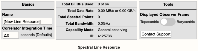
Basics Table
Near the top you will find the Basics info table (Figure 3.3.3a) which is common across all tabs. This is where you can change the name of the resource and the correlator integration time.
 |
|
Figure 3.3.3a: Spectral line Basics info table. |
Below is a description of the parameters in the Basics table.
| Name |
Be sure to use unique names for all different resource setups and do not use special characters. |
| Correlator Integration Time (seconds) |
The correlator integration time would have been set when the resource was initially created by selecting one of the array configurations. This can be modified in the table if you do not wish to use a default setting. For more details, refer to the Time Resolution and Data Rates section of the Observational Status Summary (OSS). |
| Total Bl.BPs Used |
This indicates the total baseline board pairs used, i.e., correlator resources. The starting number will always be zero and will increase as lines and continuum subbands are added and when more baseline board pairs are used per line. |
| Total Data Rate |
The data rate of the resource will increase as lines and continuum subbands are added. Keep in mind the minimum and maximum data rates: Time Resolution and Data Rates. |
| Total Spectral Points |
The total spectral points will increase as the number of requested BlBPs increases. For a more detailed explanation, refer to the Spectral Line Resources section of the OPT manual. |
| Total Bandwidth (GHz) |
This will display the sum of all subband bandwidths across all basebands in GHz. |
| Capability Mode |
The will display the capability mode of a resource, e.g., general, shared risk, or resident shared risk observing. This will depend on the total data rate and certain other settings described in the OSS. |
| ID |
This is the resource ID. |
| Displayed Observer Frame |
Default is Topocentric (rest frame is the telescope and is what the VLA uses at the time of observing). This can be toggled to Barycentric (rest frame is Earth+Sun center of mass). |
| Contact Support |
Selecting this button will allow you to contact the NRAO Science Helpdesk. |
Doppler Position Tab
You must enter the coordinates of the science target (or near a grouping of science targets) in RA and Dec. This will unlock the proceeding tabs so you may continue with the creation of the resource. You can also import the RA and Dec from a source in your Source catalog.
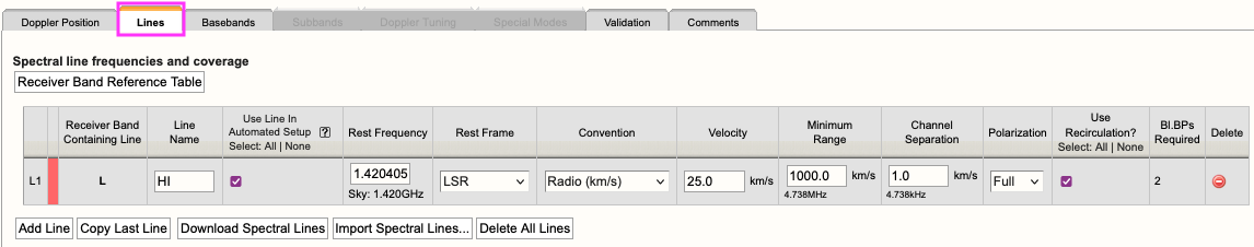
Lines Tab
In the Lines tab, you may either enter in the line information one-at-a-time by selecting Add Line or import a text file containing a list of lines by selecting:
Import Spectral Lines → Browse (select the txt file containing the lines you want to import/upload) → Upload → Done (if using Firefox)
(Note, if you are using Firefox you will be required to select the Done button after selecting Upload to complete the import. It has been determined that other browsers such as Safari (Mac), Opera (Linux / Mac / Windows), Chrome (Linux / Mac / Windows), or Microsoft Edge (Windows) do not need the Done button to be selected to complete the upload.)
Example of a spectral line added to the Lines tab can be seen in Figure 3.3.3b.
 |
|
Figure 3.3.3b: Example of a spectral line added to the Lines tab. |
For each line you will need to provide the following information:
| Line Name |
Do not use special characters and keep the name relatively short. |
| Use Line in Automated Setup (all/none) |
You may choose which lines are used in the automated setup. This means you can upload a set of lines and only use some of them or use this option as a way to partially automate/manually setup your resource. |
| Rest Frequency |
Rest frequency of the line you wish to observe in GHz. |
| Rest Frame |
LSR, Topocentric, Barycentric, Geocentric |
| Convention |
Radio (km/s), Optical (km/s), Redshift (Z), Relativistic (km/s) |
| Velocity (km/s) |
The line-of-sight velocity at which the line should be observed. |
| Minimum Range (km/s) |
Specify the minimum velocity range that should be covered. Note that a first order bandwidth for this range will be calculated using the line frequency and displayed below the input field. This will set the subband bandwidth to the next wider possible value. Try to keep the bandwidth for the range as narrow as possible for your science to maximize flexibility in placing the 128 MHz boundaries between your anticipated subbands; you can widen them later. In general pre-defining subbands wider than 32 MHz will often give problems in the initial placing of the subbands. |
| Channel Separation (km/s) |
The (maximum) channel separation input field will display the velocity width converted to frequency below the input field, and set the channel separation in the subband to the next possible narrower value. |
| Polarization |
Full, Dual, Right, Left |
| Use Recirculation? |
Enabled is recommended. |
| Bl.BPs (baseline board pairs) Required |
This will auto-update as the other line information is entered. |
Below is an example of a line text file for a Spectral Line resource. For more details, refer to the OPT manual. You may also export a set of lines from an existing resource.
#Line name; Rest frequency; Rest frame; Velocity convention; Velocity; Minimum range; Channel separation; Polarization products; Additional specifications
L1; 38.293GHz; Lsr Kinematic; Radio; -10.5km/s; 31.0km/s; 0.01km/s; DUAL; USE_RECIRCULATION=true
L2; 38.452629GHz; Lsr Kinematic; Radio; -10.5km/s; 31.0km/s; 0.01km/s; DUAL; USE_RECIRCULATION=true
Basebands Tab
There are two options for generating the spectral lines in their respective basebands, automated and manual.
Automated Setup
This will automatically generate the line coverage in their respective subbands and properly center the basebands. Only one receiver band will be activated when your lines are spread over frequencies spanning more than one band.
- If all your lines fall below 4 GHz, i.e., up to the S-band frequency range, you will only be permitted to use the 8-bit system.
- If all your lines fall within the 4-50 GHz frequency range, the RCT will select the system which best covers all of the lines. It will default to using the more line-sensitive 8-bit samplers, but in cases where necessary to cover all lines with the desired velocity coverage, it will use the 3-bit system.
- You may manually make adjustments if you do not like what the RCT has selected. However, this may result in missing some lines if you choose the 8-bit system. Keep in mind, the mixed-mode 3/8-bit system may be manually selected.
Manual Setup
This is essentially the same implementation as the original RCT and will require you to select the desired system (if applicable), set the baseband centers and generate each line/subband one-at-a-time. To see the table of lines and their respective Generate button, scroll down in the Basebands tab.
- Shifting the baseband center frequencies can be done in two ways:
- Use the '+' or '-' buttons next to the displayed baseband center frequency. This will shift the baseband center frequency by multiples of +/- 128 MHz without changing the relative location of the subbands between the 128 MHz boundaries, or;
- Manually enter the desired center frequency, with the caveat of undoing the optimization for placing the subbands away from the 128 MHz boundaries.
- If you shift the baseband center frequency or change the system after using the automated setup, you will need to manually generate a line if it resides in a different baseband.
- Be aware of subbands that "hug" a 128 MHz boundary, which is a common symptom that may indicate an unwanted (and generally unnoticed) subband shift due to changing the baseband center. Unless using the Automated Setup and possibly the +/- buttons, if a subband and 128 MHz boundary "touch" after manually shifting the subband, that subband should be regenerated manually and subsequently may issue new warning messages.
Redo Automated Setup
If you do not like the changes you made after the automated setup, you may select "Redo Automated Setup" and it will remove all manual edits to the resource. Basically, starting over with the automated setup.
Undo Manual Setup
If you wish to start over with the manual setup, then you will need to manually remove all subbands and lines from the Subbands tab. The same as you would with the original RCT; note that this can be done in bulk from the Subbands tab.
Subbands Tab
In the Subbands tab you may add continuum subbands and/or make any adjustments to the lines, i.e., bandwidth (BW), polarization, Bl.BPs (baseline board pair stacking), and Recirculation.
Spectral Line Resolution
The generated lines will appear in their respective basebands. When you see a line without a generated subband associated with it, that is simply a line guide to show you where it may overlap in that baseband. The actual generated line will be in the neighboring baseband with a similar frequency range. The user may make adjustments to the bandwidth (BW), polarization, and the resolution of a line by adjusting the number of BlBPs and recirculation. For more details on stacking BlBPs and increasing recirculation, please refer to the Recirculation vs Baselineboard Pairs section.
- If subbands overlap or are very close to each other, it may be beneficial to merge the subbands into one with a new subband center frequency and a wider bandwidth that covers the frequency ranges of the overlapping subbands — note that this typically requires to also change the recirculation factor and/or the number of baseline board pairs to keep the channel separation the same as in the original subbands.
- You may also shift the baseband center frequency by +/- 128MHz from within the Subbands tab. (Again, you may need to manually generate a line if it resides in a new baseband.)
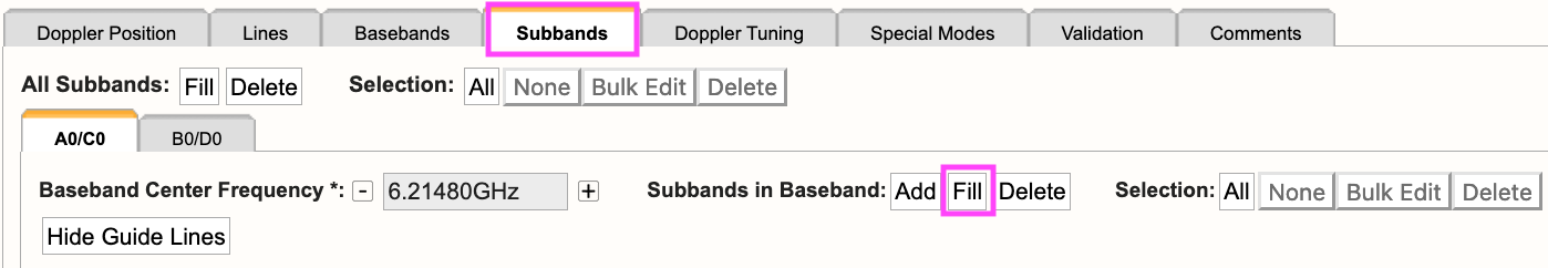
Add Continuum Subbands
For each baseband, continuum subbands can be added one-at-a-time or use the recommended Fill button at the "Subbands in Basebands" level (see Figure 3.3.3c). Note, the bulk edit mode of the Fill option will not alter the generated spectral lines.
Manually adding subbands one-at-a-time will require the user to select the Add button, then select the central frequency range of each continuum subband by choosing the desired range in the drop-down menu located in the subbands table.
 |
|
Figure 3.3.3c: Adding continuum subbands in the Subbands tab using Fill. |
After selecting Fill, the user will be presented with a pop-up box containing the following parameters:
| Bandwidth |
This defines the bandwidth of each continuum subband. |
| Number of Subbands |
The maximum number of subbands per baseband will vary depending on the sampler mode (3-bit or 8-bit) and how many baseline board pairs have been used so far by the generated spectral lines. |
| BlBPs |
Number of baseline board pairs to stack per subband. |
| Polarization |
Full (RR, LL, RL, and LR), Dual (RR and LL), or single (RR or LL) |
| Array Summing |
None should be used for spectral line resources. |
| Recirculation |
This can be utilized per subband to increase the resolution without increasing the number of BlBPs, i.e., correlator resources. |
| Place first subband in Grid |
The default is to start at the #2 subband. You may change this to start at a different subband, e.g., #1. |
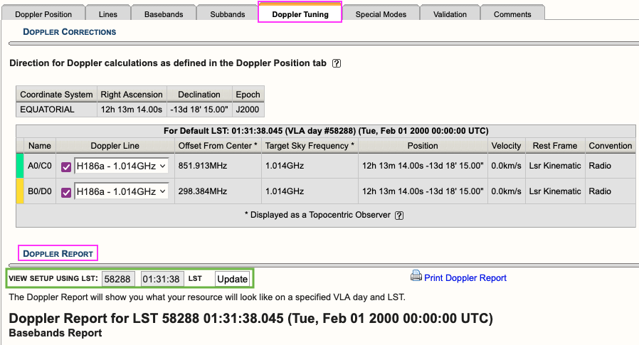
Doppler Tuning Tab
You are required to enable the Doppler tuning for at least one baseband doing so will also enable a Doppler Report located below the Doppler tuning settings (see Figure 3.3.3d).
 |
|
Figure 3.3.3d: Doppler Tuning tab showing an example of a Doppler Report. |
You may update the report to view the setup for a given VLA LST day and time. This will recalculate the values in the baseband tables below and will allow you to see what the on-the-sky values ("Script Computed Center Frequency" column) will be on the set day and time. The default values are 58288 01:31:38 LST which translates to 2000Feb01 00:00:00 UT.
Special Modes Tab
RFI blanking can be enabled for the entire resource. For more details, refer to the RFI Blanking section.
Validation Tab
If the resource does not validate and it's not clear why, contact the NRAO Science Helpdesk via the RCT. Contacting us via the RCT will append a log file to the ticket so we can take a deeper dive into the resource errors.
Comments Tab
You may provide comments as notes to yourself for future reference.


Connect with NRAO