VLBA Calibrator Search Tool
VLBA Calibrator Search Tool User’s Guide
The new VLBA Calibrator Search Tool is a versatile tool that allows users to identify candidate calibrator sources for their VLBA observations. Users can limit the results by specifying a minimum flux density, observing band, and angular separation from the science target. Users can sort the results by angular separation from the science target (default), flux density (short or long baseline, any band), or position uncertainty.
The Search Page
The front page of the VLBA Calibrator Search Tool is the search page. Here, users enter the information about their science target to start the process of finding candidate calibrator sources for their observations.
1. Enter the Right Ascension (RA) of the science target.
The search tool accepts inputs in the formats XX:YY:ZZ.ZZZ, XXhYYmZZ.ZZZs, XX YY ZZ.ZZZ, or XX YY. Users can enter as many digits beyond the decimal on the seconds value as they wish. If the seconds are omitted (XX YY), the tool will assume the seconds are 00.0.
Example RA entries:
13:31:08.288
13h31m08.29s
13 31 08.3
13 31
2. Enter the Declination (DEC) of the science target.
The search tool accepts inputs in the formats XX:YY:ZZ.ZZZ, XXdYY’ZZ.ZZZ”, XX YY ZZ.ZZZ, or XX YY. Similar to entering the Right Ascension values, users can enter as many digits as they wish after the decimal point for arcseconds. If the arcseconds are omitted (XX YY), the tool will assume the arcseconds value is 00.0.
Example DEC entries:
30:30:32.959
30d30'32.96"
30 30 32.9
30 30
3. Enter the search radius in degrees.
The default search radius is 6 degrees, but users can enter any number between 0.0 and 45.0 degrees.
4. Enter the maximum number of sources to be returned.
The default is 20, but users can enter a number as small as 1 or as large as 100.
5. Enter the minimum flux density of the sources to be returned.
The default minimum flux density is 0.0 Jy, but users can enter any positive value they wish. This will limit the returned sources to only those with a flux density of at least the value entered. The tool uses the short baseline flux density (<400 km) values for this filter.
6. Choose an observing band.
This is used in combination with the minimum flux density above. If a band is specified, the tool will filter the flux density at that band. If a source does not have an entry for the specified band, the tool will look at the next closest band.
For example, suppose a user selects the 6cm band (C-band) and a source does not have a flux density entry for 6cm, but it does have a 4cm (X-band) entry. The tool would filter based on the 4cm flux density entry for the source in this case.
The default Observing Band is “Any”. In this case, the tool will filter sources based on the maximum short baseline flux density entry across all bands.
7. Execute the search.
Once all fields are filled, click “Search” at the bottom of the page. The tool will initiate the database query and return a table of sources that meet the specified requirements in a new page.
Example of a Filled Search Form
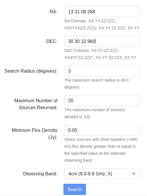
Figure 1 (below) shows an example of a filled search form. The RA and DEC fields use the XX YY ZZ.ZZZ format. The user has opted to limit the search radius to 3 degrees. The number of returned sources is capped at 20 (the default). The user has required that the returned sources have a short baseline flux density of at least 0.05 Jy in the 4cm band (X-band).
The Results Page
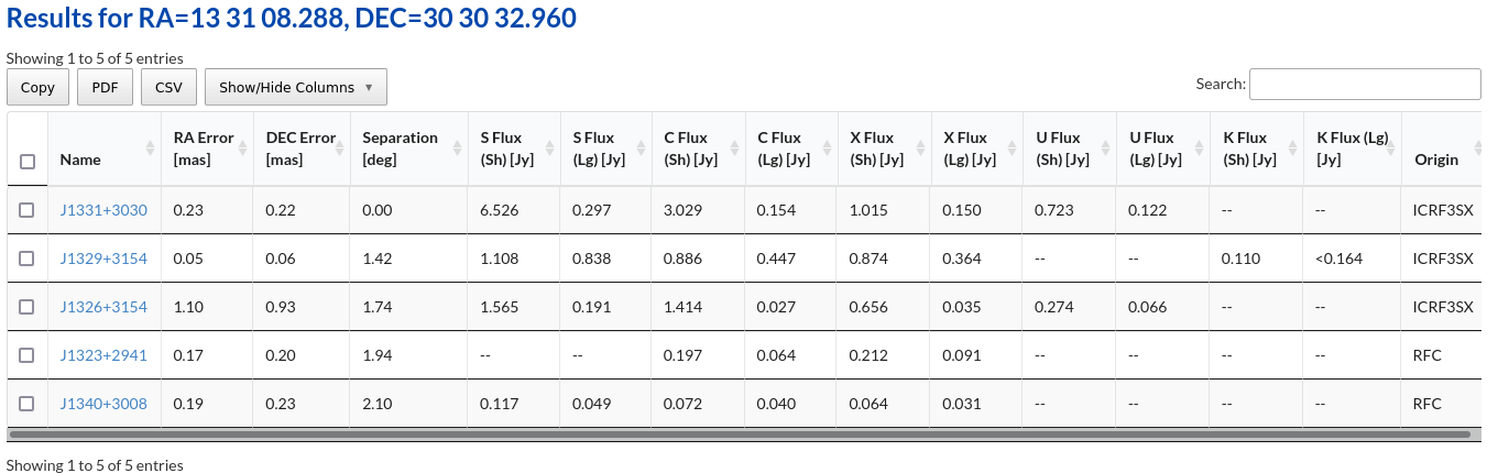
The returned sources are presented in a table in a new page (see Figure 2 below for an example). The default sorting is by angular separation from the input coordinates, with closer sources listed first. Users can sort the table entries by clicking on any column heading. Sorting the table does not perform a new search, but only reorders the returned sources based on the values in the selected column.
The flux density measurements presented are from the Radio Fundamental Catalog (RFC; maintained by L. Petrov).
All flux density values presented in the table are averages over time, and some values may not accurately represent the current flux density of the source at that band. Users are encouraged to carefully evaluate all potential calibrator sources.
A “Show/Hide Columns” drop-down menu is located above the table. Users can hide any columns they do not find useful.
To the left of each source name is a check box. Users can click the check box to select the source. Click “Copy” to copy all selected sources to the clipboard (to paste into a text or word processing document). Click “PDF” to write all selected sources to a PDF file. Click “CSV” to write all selected sources to a comma-separated variable (.csv) file.
Clicking on a source name will redirect users to a new page with information for that specific source. The individual source page will contain more information than what is presented in the table (see the next section).
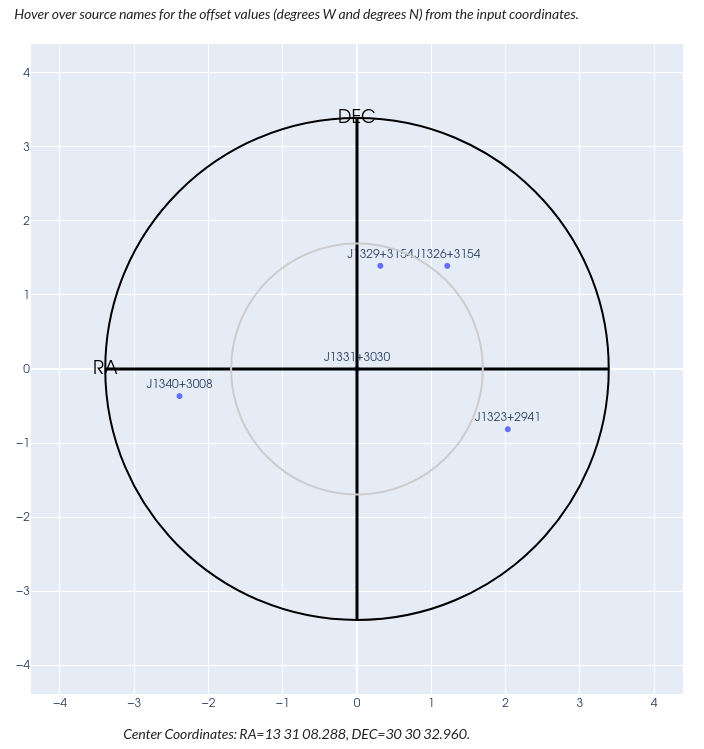
Under the table, users will find a radial plot (see Figure 3 below) showing the relative positions of all the returned sources. The center of the plot corresponds to the input coordinates for the search. Hovering over the source name will display the relative x and y values (in degrees) used for the plot. NOTE: The radial plot may look very odd if users are searching near the poles (+/- 90 degrees declination).
Individual Source Pages
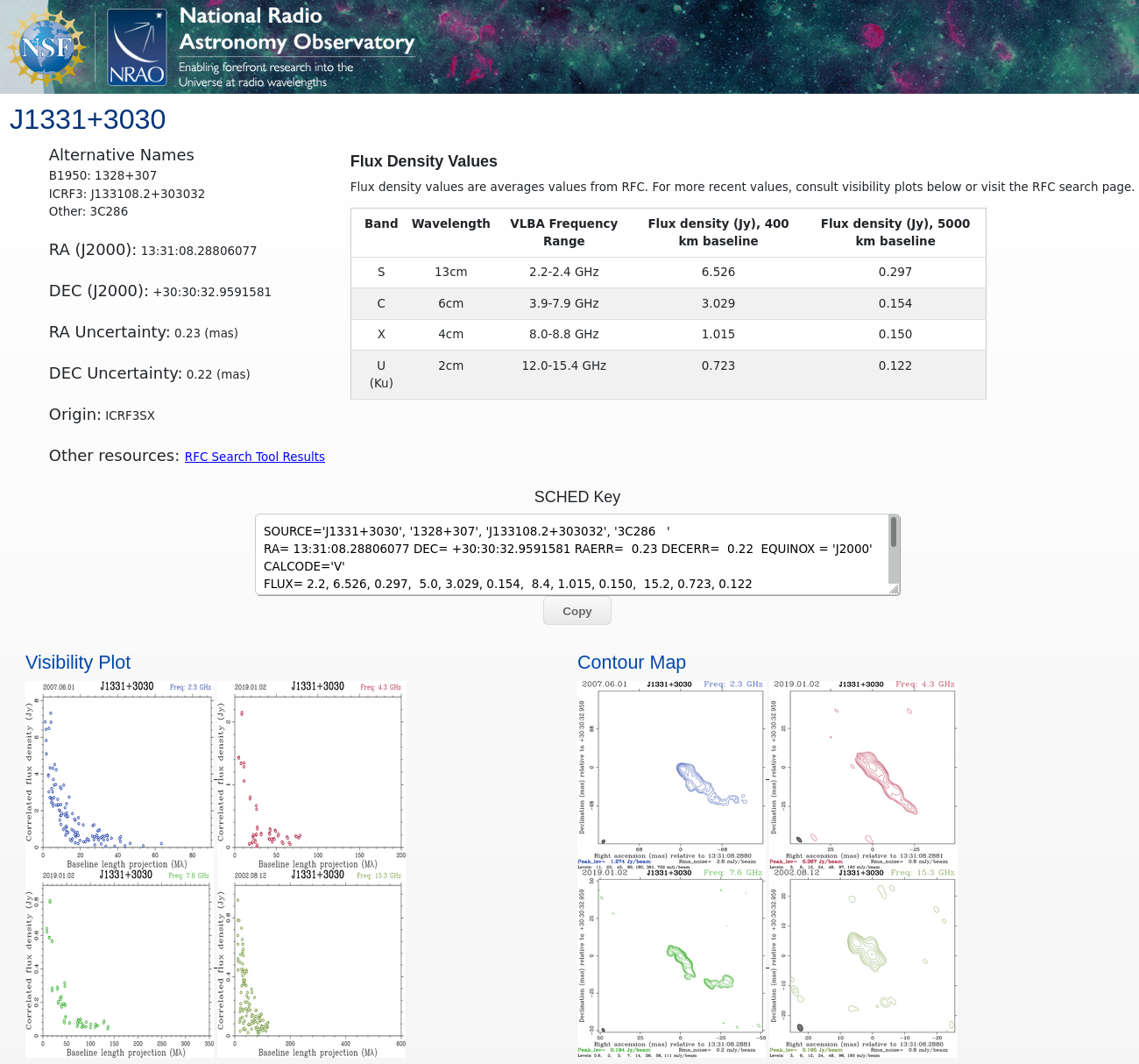
Clicking on the source name in the Results table will take users to a new page with more details for that specific source. The source name is at the top of the page, with several alternative names listed below (when appropriate). The full RA and Dec values, and their associated uncertainties, are listed below the name(s). The "Origin" gives the reference for the source coordinates (e.g., ICRF3 S/X). All available flux density measurements are presented in a table to the right. As mentioned in the previous section, the flux density values in this table are averages over time and may not accurately represent the current flux density of the source. Users are encouraged to inspect the Visibility Plots at the bottom of the page.
If users wish to see entries from sources nearby in the RFC, they can click on the “RFC Search Tool Results” link. This will take users to an RFC search around the current source coordinates. Users may find this useful because the RFC often contains historical flux density measurements for sources, which are a good way to look for variability in the source and compare the most recent measurements to the average values reported in the table.
The “SCHED Key” section contains the detailed information about the source in a SCHED .key format. Users can copy the data and paste it into a .key file to build their own catalog of sources.
At the bottom of the page, users will find several useful plots. The Visibility Plots show the amplitude versus baseline length (in units of wavelength) for the source at several bands. These plots are often more reliable estimates of the current flux density of the source. Check the top of the plots for the date and band.
The Contour Maps are presented to give users an estimate for the source structure at various frequencies.
Clicking on any of the plots or maps will open a larger version.
The Visibility Plots and Contour Maps are both obtained from the RFC and are presented in the VLBA Calibrator Search Tool with permission from L. Petrov.
Figure 4 (below) shows the individual source page for 3C286 (alert readers may have recognized the coordinates used in the example of the filled search form).
Reporting Issues and Getting Assistance
Users who experience any problems with the VLBA Calibrator Search Tool are encouraged to report these issues via the NRAO helpdesk using the "VLBA Calibrator Search Tool Feedback" department. The helpdesk is also an excellent resource for users requiring assistance selecting a good calibrator.
Other Calibrator Search Tools
Users may wish to use other search tools to identify candidate calibrators, or to find more information on certain sources.
The Radio Fundamental Catalog VLBI Calibrator Search Tool
L. Petrov maintains NASA's Radio Fundamental Catalog (RFC) and provides a useful VLBI Calibrator Search Tool to query the RFC. The RFC is updated on a quarterly basis. One of the major advantages of the RFC search tool is that it provides historical flux density measurements for the sources, which allows users to identify which sources are known to be highly variable. A link to a search of the RFC near a source's location is provided on the Individual Source Page of the VLBA Calibrator Search Tool to allow users to easily access the historical flux density measurements.
The Bordeaux VLBI Image Database
The Bordeaux VLBI Image Database (BVID) contains VLBI images of thousands of sources. The sources in the BVID are mostly very bright objects used in the International Celestial Reference Frame (ICRF). Like the RFC, the BVID gives users access to historical information on the sources. Users can look for morphological changes, as well as flux density variability. Users can search the BVID by source name, source coordinates, observation date, and several other criteria (see the "MULTI-CRITERIA" tab on the BVID search page).
Tips for Selecting Calibrator Sources
VLBA users will often need to observe several different calibration sources throughout the course of an observation. Here are some tips on choosing the optimal calibrator for each purpose.
Phase Reference Calibrators
Phase reference calibrators should be as close to the science target as possible. The typical recommendation is that a phase reference calibrator should be within 5.7 degrees of the science target. However, this is highly dependent on the observing band and the elevation of the science target. Observations at frequencies lower than 4 GHz should use phase reference calibrators that are no more than 4 degrees from the science target. If the science target will be at lower elevations (less than ~30 degrees) for a significant portion of the observation, the phase reference calibrator should be closer than the nominally recommended separation. In general, users should pick the closest phase reference calibrator that is bright enough for their observation.
For more details on choosing a phase reference calibrator and building a phase-referenced observing schedule, see the Guide to Observing with the VLBA - Calibration Strategies.
Fringe Finder Calibrators
Fringe finders should be very bright (>1 Jy) on all baselines. In general, a compact (point-like) source is preferred. However, sources with significant structure (e.g., jets) can be used as long as there is sufficient flux on all baselines.
The NRAO maintains a list of recommended fringe finders, but the VLBA Calibrator Search Tool can also be used to identify other sources that may work better for a specific observation. To search for candidate fringe finders, set the minimum flux density to 1 Jy (or larger), select the observing band (if desired), and set the search radius to a large value (20 degrees will often be large enough, but larger values will return more options).
For more information on identifying a good fringe finder and including fringe finder scans in an observing schedule, see the Guide to Observing with the VLBA - Calibration Strategies.
Bandpass Calibrators
Bandpass calibrators should be very bright (>1 Jy) on all baselines. This ensures that there is sufficient signal-to-noise to correct for the shape of the bandpass during calibration. For many users, the bandpass calibrator and the fringe finder will be the same source. For more information about picking a good bandpass calibrator and including bandpass calibration scans in an observing schedule, see the Guide to Observing with the VLBA - Calibration Strategies.
Requesting Observing Time to Identify Calibrators
As part of the proposal process, users may request extra observing time to identify a suitable calibrator. On the Technical Justification, there is a section that says:
"Note whether the target(s) can be self-calibrated and estimate their flux density. If phase-referencing is required, specify the phase-reference calibrators to be used and their expected flux densities, or whether extra time (on the VLBA or VLA) will be required to find calibrators:"
(Emphasis added.)
Additionally, users can contact VLBA staff via the NRAO helpdesk at any time to request short observations of candidate calibrator sources.
Users can request a small amount of time to get snapshots of a few candidate calibrators. Projects with a small number of science targets should be able to identify the necessary calibrators with ~1 hour of observing time. More complicated projects (e.g., many sources across the sky) may need more time. Nearly all of the VLBA calibrator sources are known to be variable at some level, and verifying that a candidate is bright and compact enough to use for a specific project prior to the full observation is always advantageous. It is especially important to check the candidate calibrators when previous observations at the project's observing band are not available (e.g., L-band).


Connect with NRAO