VLA + LWA Observing
Disclaimer: Non-standard eLWA observing is currently listed as RSRO (Resident-Shared Risk Observing) and not GO (General Observing). A fixed version of this mode is available as Shared Risk Observing as of semester 2022A and available from the list of default setups, labeled as "eLWA (from semester 22A)". If you have questions regarding eLWA observing, please contact us through the NRAO Science Helpdesk.
VDIF stands for VLBI Data Interchange Format and was introduced in 2009 to standardize data transfer and storage for Very Long Baseline Interferometry (VLBI) observations. The expanded Long Wavelength Array (VLA + LWA = eLWA) observing mode uses this format to record a VDIF data stream for each VLA antenna. The VDIF files are then combined with raw voltage beam data from the New Mexico Long Wavelength Array stations and are correlated offline using a software correlator after the observation is completed.
The Fundamental Steps for Creating an eLWA SB
Step 1: Create VDIF Instrument Setup
First, go to Instrument Configurations (RCT), select the resource catalog you wish to create a new resource, and select FILE → CREATE NEW → 8-BIT INSTRUMENT CONFIGURATION.
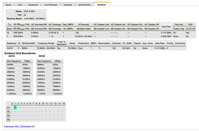
- Basics tab: Give the resource a name, e.g., VDIF 8 MHz, then select the receiver band 4 (54.0 - 86.0 MHz). The correlator integration time in this case is not relevant, just specify 5.0 seconds.
- Basebands tab: Set the center frequencies to 536.0 MHz.
- Subbands tab: Add one subband, select 8 MHz bandwidth, put BB_center-460.0 MHz to set central frequency to 76 MHz, and then set polarization to Dual and Recirculation to 1x.
- Special Modes tab: Select the VDIF tab and select Yes for Recording.
- Validate tab: Make sure the summary looks like Figure 4.9.7a shown below and no validation errors are reported.
 |
|---|
| Figure 4.9.7a: Validation page in the Resource Catalog Tool (RCT) of a valid VDIF resource. |
Step 2: Enable scan for VDIF recording
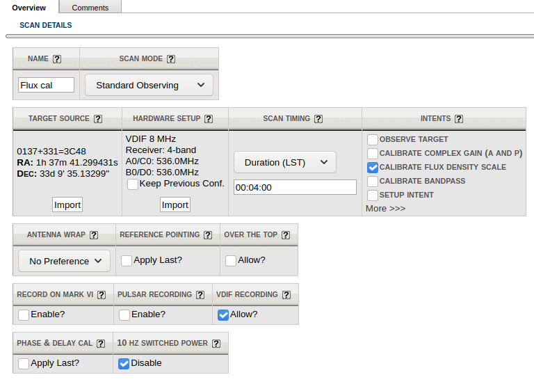
When creating a new scan, select the above created VDIF instrument configuration. In order to enable VDIF recording, you also need to set the checkbox for VDIF Recording within the scan and it is also strongly recommended to disable the 10 Hz switched power, by selecting the Disable checkbox. Your scan should look similar to the example in Figure 4.9.7b below.
 |
|---|
| Figure 4.9.7b: Example of a scan using VDIF recording. |
Important Note: If you plan to trigger resetting requantizers using a setup scan and the VDIF recording instrument configuration, then 10 HZ SWITCHED POWER must be unchecked, to have switched power enabled, and VDIF RECORDING should be disabled by leaving it unchecked.


Connect with NRAO